

Kenya certificate of Secondary Education
2016 Physics paper 3
1. You are provided with the following:
– A triangular glass prism
– A piece of soft board
– Four optical pins
– Four office pins
– A sheet of plain paper
– A voltmeter
– An ammeter
– A galvanometer
– Two cells and two cell holders
– A resistance wire mounted on a copper wire labelled C
– A reance wire labelled
– A switch
– Connecting
– A glass tube
PART A
Proceed as follows:
(a) Place the plain sheet of paper on the soft board and pin it using the office pins at the corners. Trace the triangular prism outline of the prism on the sheet of paper (use the upper part to leave space for two other outlines on the same page).
Label the vertices of the outline at A, B and C. Remove the prism from the paper.
(b) On the outline at a point 0 near the centre of side AB draw a normal ON.
(c) Draw a line PO at an angle of 30° to the normal ON as shown in Figure 1.
(d) Replace the prism accurately on the outline. Fix two optical pins vertically on line PO at different points (see Figure 1).
(c) View the images of the two pins through side AC of the outline. Fix a third and fourth pin vertically such that they are in line with the images of the first and second pin. Remove the prism and the pins.
Draw a line joining the marks made by the third and fourth pins and extend it to join line PO (also extended) as shown in Figure 1.(1 mark)

Measure F, the angle of deviation of the emergent ray. (2 marks) (f) Repeat part (e) for other angles of incidence shown in Table 1. (Draw a fresh outline of the prism for each angle of incidence) Complete table 1 (3 marks)

(g) Determine: (i) E the angle of emergence (between the emergent ray and the normal at the point of emergence) at the least angle of deviation. (2 marks)
(ii) K given that K = 2 sin

(where Fo is the least angle of deviation). 2J (2 marks)
PART B
Proceed as follows:
Set up the circuit shown in Figure 2.

(S is a point on wire FH such that SH = 30 cm).
(h) Close the switch. Adjust the position of Clip X along FH until the current is 0.2A.
Record the potential difference (V) across length SH in Table 2.
Repeat part (a) for the values of current in Table 2. Complete Table 2 (4 marks)

(j) Determine Rm, the mean resistance of wire SH. (1 mark)
(k) Open the switch, disconnect the voltmeter and remove the cells.
(1) Using a glass rod, wind the copper wire (C) into a coil.
Slightly pull out the ends to ensure that adjacent turns of the coil do not touch.
(m) Join the coil to the resistance wire R by winding about 1 cm of the coil end onto one end of resistance wire R (see Figure 3). Coil R —10WQ(8)00 Figure 3

Close the switch and adjust clip X to a point 0 along FH so that the current is now 0.1 A. Record the centimetre mark of point 0.
Centimetre mark of point 0 cm.
(o) Move the jockey along OH and obtain a point T, where the galvanometer reads zero.
Record the centimetre mark of T2 Centimetre mark of T2 cm (1 mark) Determine length Lc of OT, Lc = (1 mark)
(p) Connect clip Y at U and clip Z at V and repeat part (h) to obtain the point T, (where the galvanometer reads zero), the balance point of wire R. Record the centimetre mark of T, for R.
Centimetre mark of T — cm (q) Determine the balance length LR for the resistance wire R LR
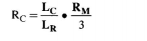
r) Determine the constant Rcgiven that:
2. You are provided with the following:
– Two half metre rules
– One metre rule
– One stopwatch
– Two pieces of thread
– Some sellotape
– Stand boss and clamp Proceed as follows:
(a) Using the retort stand, clamp one half-metre rule at its centre, such that the scale is horizontal in a vertical plane (see Figure 5).
Using sellotape and two strings, suspend the second half-metre rule in a horizontal plane such that;
(i) its scale is horizontal
(ii) the strings are equidistant from the centres of the half-metre rules and distance = 40 cm apart.
(iii) The height between the two half-metre rules is L = 65cm. (see Figure 5).

(b) Set the suspended rule into small oscillations in a horizontal plane about a vertical axis through its centre. (see Figure 5).
(c) (i) using the stopwatch, record the time t, for oscillations. t1 = s (1 mark) (ii) Determine the period T, the time for one oscillation.
Ti = (1 mark) (d) With I still at 65 cm, change the distance between the strings from 40cm to d, = 20 cm. Repeat part C to obtain period T,. T2 = (1 mark)
(e) Determine constant r given that (2 marks)

For the rest of the experiment the distance between the strings should remain 20cm.
(f) Repeat part (c) for values of / Shown in Table 3. Complete Table 3 (6 marks)

(g) Plot a graph of log T(y axis)against log L
