
Definition of terms used in networking.
A computer network can be defined as a collection of computers linked together using transmission media for the purpose of communication and resource sharing. The term transmission media refers to any physical or non-physical link between two or more computers and in which a signal can be made to flow from source to destination. Some of the shared resources include programs, printers,storage devices, communication links etc.
Data communication
Data communication refers to the process of transmitting data signal from one point to another through the network. If all aspects related to data communication are taken into consideration, computer networking is the most recent, efficient and reliable means of transmitting data.
Terms used in data communication
Some of the terms used in data communication include: data signal, signal modulation and demodulation, multiplexing, bandwidth, base band, broadband transmission and attenuation.
Data signal: A data signal is a voltage level in the circuit which represents the flow of data. In data communication, data signals can either be analog or digital in nature. Analog data is made up of continuous varying waveform while digital data is made up of a non-continuous discrete waveform.
Signal modulation and demodulation: This is the process of converting data signals to a form that is suitable or transmission over a transmission medium. For example, a modem converts a digital signal to analog by superimposing it on an analog carrier signal which can be transmitted over analog telephone lines. This process is called modulation. A modem at the receiving end converts the analog signal into digital form, a process known as demodulation.
Multiplexing: Multiplexing is the process of sending multiple data signals over the same medium e.g. a wire conductor can be made to carry several data signals either simultaneously or at different times. Demultiplexing is the process of separating the multiplexed signals at the receiving end. Imagine a situation where one hundred computers in town A want to communicate with others of equal number in town B. If multiplexing is not used, each of the computers in town A will need a direct cable linking it to its partner in town B! However, with multiplexing, the computers can be made to share a single cable laid between the two towns hence save cost. The different frequencies create what is called different logical channels in the medium. .
Bandwidth: A bandwidth is the maximum amount of data that a transmission medium can carry at anyone time. For example, a certain cable may have a bandwidth of 100 Mbps (Mega bits per second).
Baseband signal: Baseband signal is a digital signal that is generated and applied to the transmission medium directly without modulation. The signal takes the form of voltages of different magnitudes applied to the medium. The baseband signal utilises the full capacity of the transmission medium, hence at anyone time; only one signal can be sent. However, multiple signals can be sent at different times if they are multiplexed.
Broadband transmission: In broadband transmission, an analog signal is sent over the transmission medium using a particular frequency. This means that several data signals can simultaneously be sent through the same medium but at different frequencies. Frequency bands between these data signals prevent them from overlapping.
Attenuation: This is the decrease in magnitude and energy as a signal progressively moves along a transmission medium. If the signal is not boosted, it will totally be .lost along the way and may never reach the destination. Attenuation or signal loss is usually corrected by placing signal amplifiers also called repeater stations along the medium at appropriate distances in order to receive the weak signal, clean it, amplify it then retransmit it.
Modes of data communication
There are three modes of data communication namely: simplex, half Duplex and full duplex.
Simplex transmission refers to communication in only one direction. An example of simplex communication is the normal radio or television broadcast. The listener or viewer cannot communicate back through the radio or television receiver back to the broadcaster.
Half duplex refers to communication in both directions but one direction at a time. A sender must send the data before the recipient can reply. For example, if two police officers are communicating using a ‘walkie talkie’ radio, one has to say “over” to mark the end of every statement in order for the other to respond.
Full duplex communication occurs in both directions simultaneously. An example of full duplex communication can be found in computers that are sending and receiving data on a network.
Types of computer networks
Computer networks can be classified using several aspects but the most common classification is according to size. Currently, there are several types of networks but the three most common are:
- Local area network (LAN)
- Metropolitan area network (MAN)
- Wide area network (WAN)
Local area network (LAN)
Local area network is a computer network that spans a relatively small geographical area like in one building or a school. One local area network can be connected to other local area network over any distance via data transmission lines or wireless media.
Most local area networks connect personal computers and server computers on a small network. A server computer is a computer dedicated to servicing requests for resources from other computers (workstations) on a network. Most local area networks are configured such that each workstation has its own central processing unit with which it executes programs, but it is also able to access data and devices anywhere on the local area network. Local area networks enable many users- to share expensive devices, such as laser printers, as well as data. Users can also use the local area network to communicate with each other, by sending messages or engaging in chat sessions. Local area networks are capable of transmitting data at very fast rates, much faster than data transmitted over telephone lines. .
Metropolitan area networks (MAN)
A metropolitan area network is a network that covers a metropolitan area like a town or city. The metropolitan area network size typically covers a radius of between 5 to 50 km. The metropolitan area network infrastructure may be owned by a single company that has offices across a metropolitan area or by a service provider who provides network services to subscribers in the area. In essence, a metropolitan area network is made up of many local area networks in a metropolitan area.
Wide area networks (WAN)
A wide area net work is larger than a metropolitan area network and covers a large geographical area such as a country, a continent or the whole world. It consists of many local area networks and metropolitan area networks connected together to form one large network such as the Internet.
Purpose and limitations of networking
Purpose of networking
Some of the reasons for setting up computer networks include: resource sharing, remote communication, distributed processing facilities, cost effectiveness and reliability.
Resource sharing
A resource in the network environment means data/information, files, printers, modems, communication links, storage devices, fax machines, application programs and any other component that can’ be attached to the network for access by users.
Take for example an office setup where a number of users in a small business require access to. Common information. As long as all the computers are connected, they can share their files, exchange mail, send,
Faxes, schedule meetings and print documents from any point on the network. Users do not need to transfer files via removable storage but would send the work to a network printer. This centralised access to data and information leads to less waste of time and hence greater productivity.
Imagine the benefits of a user being able to directly fax a document from the softcopy in his/her word processor, rather than having to print it out, and then feed it into the fax machine.
In most network arrangements, the shared resources may be attached to a network server. The other computers on the network that send requests to the server are referred to as clients or workstations. Network servers run a special program called the server software which controls computers on the network and listens to client requests to service them over the network. For example, a print server will give permission for a particular client to print documents on the network printer. Figure 1.2 shows a simple diagram representing a computer network that is controlled by a server.
Remote communications
In the present computing environment, computer engineers are faced with two basic problems.
- Roaming of officers who by virtue of their work keep on covering long distances away from the workplace.
- Access to the organization’s information resources so that they can have up-to-date data or at least update the information servers with the status quo in the field.
Initially, the problem of roaming was addressed by the development of portable computers like laptops. But problem of access to the network’s information server remained! However, both problems have been addressed by remote communication. Remote communication refers to the transmission of data signals between two communication devices located at different geographical locations. A computer that tries to access resources from another computer on the network is called a remote client while the computer being accessed is called a remote host. Remote communication has been made possible by use of wireless transmission media such as radio waves, microwave and satellite as will be discussed in details later.
It is through remote communications that people can be able to share ideas and pass messages over the Internet.
Therefore, remote communications give a lot of freedom to the network users which translates to more productivity. Imagine continuing to work from home just as if you were in your office.
Distributed processing facilities
Distributed processing refers to the act of running the same programs or databases on different computers which are on the same network. However, users will not know that the processing is distributed but will think that everything is taking place on computer. The output can then be transmitted to another computer or the central computer on an organisations network. Before the advent of distributed processing, many organisations had centralised systems of management. This meant that all the data and information were sent from the dumb terminal (workstation with no processing power) for processing and storage in a central computer. It therefore followed that processing of data, release of information and decision making was centralised too.
However, with distributed processing, files reside on the user’s computer rather than on a central computer. Branch offices in a large organization have their own servers that store data, information and other resources required for their daily operations. These servers would then periodically update the central computer.
This model of data processing has a number of advantages. These include:
- The failure of the central computer does not affect the operations of the other terminals.
- Processing load is shared equally hence no time wastage.
Cost effectiveness
Networks are cost effective in the organization. Although the initial purchase and lying down of network components may be expensive, the savings experienced and the value added to service delivery make them a ready choice for enterprising managers.
One good thing about a network is that it greatly increases the efficient use of scarce resources. Imagine a large organization that has stand alone computers only. In such a case, the management has to buy a printer for each computer. However, with a network, only one printer is sufficient. The same applies to other resources like fax machines, optical drives, files and applications.
It should also be noted that computer networks have enhanced daily communication by providing a paperless communication environment. Users can send electronic messages and mail to each other instead of having to bear the cost of stamp duty or delivery charges. On the same note, company executives may not need to travel across continents to hold meetings. They can hold electronic video conferences instead and save the fare.
Reliability
A computer network is reliable in two ways especially when communicating or accessing information:
- Data can be transferred with minimum error from source to destination.
- In case one computer breaks down, a user can still access data and information from the other computers using another computer on the network.
Limitations of networking
Although networking has many advantages it also offers many challenges that are associated with implementation and human factors. Some of the limitations and disadvantages of networking include security issues, high initial installation cost, moral and cultural effects, spread of terrorism and drug trafficking and over reliance on networks among others.
Security issues
Data and information held on a network is prone to more illegal access threats than if the computer was not on the network. For example, a stand alone computer may be accessed by only a few people at home or in the office environment. However, once the computer is connected to the network, especially the Internet, many people can access it not only physically but also virtually over the network. Apart from this, when information is sent over the network from source to destination, it can be tapped or listened to by unauthorized parties.
Organisations find it very challenging to guard information systems from constant threats of illegal access. One of the common methods of data protection in a networked environment is encryption. This is the scrambling of information into a complex unintelligible form. Encrypted data cannot be understood by people who illegally access it unless they have the decryption key.
High initial cost
The initial cost of buying network hardware and software is very high. In fact, most institutions that have not set up their networks more often than not quote prohibitive cost as a limiting factor.
Moral and cultural effects
Large networks like the Internet have chat rooms and messaging services that may enable underage children to meet peers and adults on the net some of whom may have bad intentions. Access to pornographic and other negative material has also made the fight against social problems such as HIV/AIDS, bad sexual behaviour, drugs and substance abuse more complicated.
Spread of terrorism and drug trafficking
The Internet provides a rich recruitment ground for all types of illegal activities such as terrorism and drug trafficking. The easy flow of information from one place to another keeps even those who are on the wrong side of the law communicating easily. Terrorists and drug traffickers use information networks for their business communications. However, many countries have come up with methods of policing the Internet to try and break such syndicates.
Over-reliance on networks
Modem organisations have phased out most manual operations this means that all business processes and the society depend on computer networks. The disadvantage of this over reliance is that if by any chance the network fails or goes down, then many systems in the society can be brought to a halt! For instance, imagine the chaos if mobile phone services were to be abruptly brought to a halt. However, proper systems and network planning should be made to avoid such occurrences.
Elements of networking
A computer network is made up of several standard elements (components) which can be classified into three major categories namely:
- Data communication media.
- Communication devices.
- Networking software.
Data communication media
A data signal cannot be sent from one place to another without a medium of communication. A data communication medium is a pathway used for carrying data and information from one point to another. The communication medium will more often than not dictate the type of signal that will be used to transmit a message. In essence, data communication media can be divided into two: 1. Communication using cable (bounded media)
Wireless communication (unbounded media)
Communication using cables (bounded media)
The main distinguishing characteristic of bounded media is that data signals are transmitted from the source to the destination through a restricted pathway such as through a cable. For example, if the cable is a copper conductor, the data signal which may be in form of an electrical signal is propagated through the cable from the source to the destination. Any radiation from the guided medium is regarded as signal loss.
There are several types of bounded transmission media but the most common ones are:
- Two wire open lines cables.
- Twisted pair cables.
- Coaxial cables.
- Fiber optic cables.
Two wire open lines cables
Two wire open lines cables are made up of two parallel copper wires separated by a plastic insulator they are used in telecommunication network to transmit voice signal e.g.
the line running from a subscriber’s house to the nearest telephone post.
Although the plastic insulator is meant to reduce inter-line interference called crosstalk their linear nature allows an electromagnetic field to build around them during heavy data transmission which may cause interference to the signal. The wires also capture environmental frequencies e.g. radio waves hence causing noise in the transmission channel. In data communications, the word noise refers to random unwanted signals picked up by the channel.
Twisted pair cables
A twisted pair cable is made up of two solid copper wire strands wound around each other in a double helix manner the winding of the wires is meant to reduce the development of an electromagnetic field around the two wires as they transmit data. These cables are mostly used to transmit both voice and data signals. The two common types of twisted pair cables are the unshielded twisted pair (UTP) and shielded twisted pair (STP) Unshielded twisted pair (UTP) cables do not have a shield that prevents electromagnetic interference (EMI) also called “electric noise” from the environment. The cable is therefore susceptible to noise and signal interference. Noise may come from lightening sparks, radio signal and even the radiations from spark plugs in motor vehicles. Unshielded twisted pair is therefore not suitable for environments that are electrically “noisy”.
Shielded twisted pair (STP) is similar to unshielded twisted pair except that a braided shield is wrapped around the wires to shield or protect them from noise.
Twisted pair cables are categorised into five groups according to the type of data transmitted and maximum rate of transmission, as shown below.
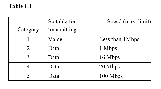
Mbps means Megabits per second. 2. Today’s networks are approaching speeds of Gigabits per second.
Most organisations today use category 5 twisted pair cables to set up their local area networks. Although twisted pair cables can support high data rates (bandwidth) of up to 100 Mbps, they suffer from attenuation. For every cable length of 90 m, a device for restoring the signal called a “repeater” is needed to amplify the signal.
The advantages of twisted pair cabling include:
- Telephone systems use UTP which is present in most buildings. This means that it is easier to set up network media because connection is readily available.
- Installation equipment is cheap and readily available.
- It is cheap because of mass production for telephone use.
The disadvantages of twisted pair cabling include:
- It suffers high attenuation.
- It is sensitive to electromagnetic interference and eavesdropping.
- It has low data transmission rates as compared to other cables.
Coaxial cables
A coaxial cable resembles the cable that is used to connect television antenna to a television set. This cable has a central copper core which may be of solid or stranded wires surrounded by a dielectric material (insulator). The dielectric material is then surrounded by a hollow mesh conductor which is covered by a shield making the cable more resistant to electromagnetic interference than the twisted pair cable.
The braid (or mesh conductor) is made of copper or aluminium and serves as the ground for the carrier wire. Together with the insulation and any foil shield, the braid shield protects the carrier wire from radio frequency interference (RFI) and electromagnetic interference (EMI). However, although the cable has better protection against electrical interference than the twisted pair cables, it has a moderate protection against magnetic interference. The diameter of the centre core or conductor determines the attenuation rate. The thinner the core, the higher the attenuation rate. Data is carried on the cable using direct current (dc).
Coaxial cables have bandwidths of up to 1 Gbps (Gigabits per second). Hence, they are installed in a network to form the network backbone (a link that connects two or more separate local area networks). A good example where this cables are used is connecting different networks between buildings and routing trunk calls in telecommunication companies. There are two types of coaxial cables:
- Thin coaxial cable (Thinnet). It has one dielectric insulator
- Thick coaxial cable (Thicknet). It has two dielectric insulators around the core and is thicker than the thinnet
The advantages of coaxial cables include:
- They are very stable even under high loads.
- They have a large bandwidth (up to I Gbps) compared to twisted pair.
- They can carry voice, data and video signal simultaneously.
- They are more resistant to radio and electromagnetic interference than twisted pair cables.
The disadvantages of coaxial cables include:
- Thick coaxial cable is hard to work with.
- Coaxial cables are relatively expensive to buy and to install as compared to twisted pair.
Fiber optic cables
This is one of the latest types of bounded transmission media to be developed. Instead of carrying or transmitting data signals using electronic signals, the fiber optic cable utilises light to transmit data from one point to another on the network. The electrical signals from the source are converted to light signals, and then propagated along the fiber optic cable. To convert an electric signal to light, you need a Light Emitting Diode (LED) at the transmitter. At the receiving end, a photosensitive device can be used to convert the light signals back to electric signals that can be processed by the computer.
The fiber optic cable is made up of the core, cladding, buffer, strength members and the jacket. .
The core: The core is the central part of the cable and is made of a hollow transparent plastic or glass.
Cladding: This is a single protective layer surrounding the core. It has some light bending characteristics in that, when the light tries to travel from the core to the cladding, it is redirected back to the core. This is why even if a fiber optic cable is bent into coils and a light signal is inserted at one end it will still be seen coming out from the other end.
Buffer: The buffer surrounds the cladding and its main function is to strengthen the cable.
The jacket: It is the outer covering of the cable.
Fiber optic cables are of two types namely:
- Single mode fiber.
- Multimode fiber.
The single mode fiber cable has a very narrow centre core the light in the cable can therefore take only one path through it. Because of this, it has a very low attenuation rate and is preferred for long distance transmission. It has a bandwidth of 50 Gbps which is higher than that of the twisted pair’s 100 Mbps. Single mode fiber is very expensive and requires very careful handling during installation.
A multimode fiber has a thicker core than the single mode it allows several light rays to be fed in the cable at an angle. Because of multiple light signals navigating the cable at the same time, distortion of the signal is possible. Multimode cables have a high attenuation rate and are usually used for shorter distances than single mode.
The light signal travels through the core, through a process referred to as total internal reflection. The process that causes total internal reflection is called refraction. Refraction is the bending of light when it crosses the boundary of two mediums that have different density. When light signal is inserted into the cable, it tries to cross from the core to the cladding. The light is bent back into the core hence propagates along the length of the cable
The advantages of fiber optic cabling include:
- It is immune to electromagnetic interference and eavesdropping.
- It is fast and supports high bandwidth.
- Large distance can be covered because it has low attenuation.
- Can be used in hazardous places (highly flammable) because they do not generate electrical signal.
- It is smaller and lighter than copper cable hence ideal for space limited situations.
The disadvantages of fiber optic cabling include:
- Connectivity devices and the media are expensive.
- Installation is difficult because the cable must be carefully handled.
- It is relatively complex to configure.
- A broken cable is difficult and expensive to repair.
Wireless communication (unbounded media)
Wireless or unbounded media, is a type of media that is used to transmit data from one point to another without using physical connections. In this case transmitting antenna and receiver aerial facilitate the communication. Examples of wireless transmission media include microwaves, radio waves, and infrared transmission all use different frequencies of the electromagnetic spectrum. All these waves travel at the speed of light.
Microwave transmission
Microwave frequencies range from about 3GHz to 40GHz on the electromagnetic spectrum. Due to their small wavelength, they easily release their energy in water as heat hence they are also used in making microwave ovens used as domestic kitchen appliances. However, in networking, microwaves are very suitable for point to point transmissions. This means that a signal is directed through a focused beam from transmitter to the receiver station.
Satellite communication
A satellite is a microwave relay station. The microwave earth stations have parabolic dishes with an antenna fixed on them in order to focus a narrow beam towards the satellite in space. A satellite transmission system has three main components:
- Transmitter earth station that would set up an uplink to the satellite in order to transmit data. The uplink will have a unique frequency.
- A satellite that is somewhere in an orbit that receives, amplifies and retransmits the signal to a receiving earth station via a downlink frequency that is different from that of the uplink so as to avoid interference with the uplink signal.
- Receiving earth station that would receive the sent signal on the other side of the globe.
A communication satellite is usually launched into space about 36 000 km above the earth in such a manner that its speed will be relatively equal to the rotation speed of the earth. An observer on earth will therefore, see as if the satellite is stationary in space. These types of satellites are called geostationary satellites. They are convenient because the need to keep on moving the parabolic dish in a bid to track the line of sight is eliminated. A geostationary satellite offers a large constant line of sight to earth stations. The area on earth where the line of sight can easily be located is called the satellites footprint. The satellite transmits the signal to many recipient earth stations to form a point to multipoint transmission. In multipoint transmission the transmitted signal spreads out in all directions forming a cell of access radius.
The new trends in microwave transmission have seen the use of very small aperture terminal (VSAT) technology. This very small aperture terminal refers to a very small satellite dish used both in data, radio and TV communication. Many businesses are adopting this new technology because it enables direct access to satellite communication instead of having to go through the state owned or licensed satellite gateways.
The satellite produces strong signals that can be received by a satellite dish antenna of only about 2 metres in diameter. The signals are decoded using a decoder that is plugged directly to a television set or a computer.
Radio communication
Radio waves travel just like surface water waves, i.e. they are omnidirectional. This means that they start from a central point and spread outwards in all directions. As they travel outwards, their energy spreads outwards over the covered area. The waves are radiated into the atmosphere by a radio frequency antenna at constant velocity. Radio waves are not visible to the human eye. Radio waves are used in radio and television broadcasts. Data can also be transmitted over radio waves communication channels. For example, instead of laying telephone cables between two towns that are geographically separated, radiowave transmission can be used to connect the two towns. Radio waves can be of high frequency, very high frequency or ultra-high frequency.
The high frequency (HF) radio waves signal is propagated by directing it to the ionosphere of the earth. The ionosphere will reflect it back to the earth’s surface and the receiver will pick the signal. Before the advent of satellite communication, high frequency radio was the only way of communication beyond the horizon such as communicating to a ship that is on the high seas or communication between continents. The biggest challenge of high frequency communication is the danger of signal interception by unauthorised parties.
Very high frequency (VHF) radio waves are transmitted along the earth’s surface. Due to the curvature of the earth, the signal will most likely attenuate at the horizon. This means that repeater stations have to be placed strategically to maintain a line of sight in order to receive, amplify and propagate the signal from one area to another. This technology is popular for the hand held radio devices like “walkie-talkie” radios. The range of very high frequency is limited but it is preferred to high frequency where no major obstructions are encountered on the landscape. This is because with very high frequency, it is possible to make the wave to follow a narrower and more direct path to the receiver. To overcome the obstructions on the earth surface like mountains and buildings, repeater stations are built on raised areas.
Ultra high frequency (UHF) radio waves are like very high frequency when it comes to the line of sight principle. This means that there should be no barrier between the sending and the receiving aerial. However, they require smaller aerials. Notice that the television aerial for very high frequency is bigger than the one for ultra high frequency radio waves. This is because; ultra high frequency radio waves can be made to follow an even narrower and direct path to the receiver than very high frequency radio waves. Therefore ultra high frequency is popular for horizon limited broadcasts.
One of the latest radio transmission technologies is called Bluetooth technology. Bluetooth is a worldwide and short-range radio technology that enables people to use hand held communication devices such as cell phones and personal digital assistants to access the Internet. The main idea behind Bluetooth communication is to try and define one standard that will allow all personal communication devices regardless of their differences or size to be able to communicate with each other and through wireless technology. The main component in Bluetooth is a small low power two-way radio transceiver, small enough to be inserted in small devices. A network of bluetooth-enabled devices is called a wireless personal area network (WPAN) or piconet. This is because bluetooth networks are best suited for personal or hand held devices. This has made radio transmission to become very popular in mobile communication and Internet connectivity.
Infrared transmission
Infrared waves fall just below the visible light on the electromagnetic spectrum. Just like the radio waves, infrared waves are not visible to the human eye. Communication through this medium is achieved by having infrared transmitters and receivers (transceivers). Transceivers of infrared signals must be within a line of sight in the same room. This is because unlike radio signals, infrared signals cannot penetrate obstacles like walls. However, the signal can be reflected off surfaces like walls and ceiling until they reach their destination.
An example of an infrared device is the infrared transceiver on most mobile phones. Once activated, two people in the same room can send messages to each other using infrared technology on their mobiles without going through the mobile service provider hence avoid being charged.
In computer networking environment, the technology can be used to connect devices in the same room to each other without need for cables e.g. a computer to a printer. The computers infrared transceiver must maintain a line of sight with the one for the printer.
Advantages and disadvantages of wireless communications
Wireless communication offers numerous advantages that justify the cost of laying down the network. Some of the advantages are:
- Wireless medium is flexible in operation as compared to bounded media i.e. devices can be moved around without losing access to the network. 2. Wireless networks can span large geographical areas easily.
- Wireless communication can take place via satellite even in very remote areas that do not have high cost physical infrastructure like telephone lines.
Some of the disadvantages of wireless communications include:
- It is relatively difficult to establish or configure.
- The initial cost is very high.
Communication devices
Computers and transmission media require communication devices for the network to be fully operational. These devices are more or less used as interfaces or junctions between the terminal devices. Terminal equipments are devices at both ends of the communication link such as a computer. Some examples of data communication devices include network interface cards (NIC), modems and codec’s, hubs, bridges, repeaters, routers, gateways, switches and access points. Network interface cards (NIC)
Network interface cards (NIC) create a physical link between the computer and the transmission media. A network interface card is plugged into an empty expansion slot on the motherboard. However, most computer motherboards today come ready with an onboard network interface controller. The network interface cards have ports at the back in which the terminated end of a network cable can be plugged.
Modems and codecs
A modem is an important device in the world of communication. It converts a signal from digital to analog form for the purpose of transmission over the analog media, while a codec converts an analog signal to digital form for transmission via a digital medium. A
modem can be external, an add-on card or built on the motherboard.
Hubs
A hub also called a concentrator is a component that connects computers on a network and is able to relay signals from one computer to another on the same network. A hub will usually connect networks that have a common architecture i.e. one that has the same set of communication software usually called protocols. Protocols are a set of rules that govern the communication between devices on a network. A hub transmits signals by broadcasting them to all the computers on the network. After the signal is broadcasted, the computer whose address is on the message picks the message from the network that is part of the broadcast domain. Some hubs called intelligent hubs are able to monitor the way computers are communicating on the network and keep the information in a small database of their own called a management information base (MIB). The network server can then use this information to fine-tune the network. Intelligent hubs can be able to manage a network by isolating computers that are not functioning properly. Several hubs can be connected together one after another to expand a network. However, this increases the broadcast range which may lead to broadcast storms on the network. The term broadcast storm refers to a condition where a network is overwhelmed with message broadcasts due to malfunctioning of network interface cards or hub related problems.
Bridges
This is a network device that selectively determines the appropriate network segment for which a message is meant for delivery through address filtering. Hence a bridge can divide a busy network into segments to reduce network traffic. The purpose of using a bridge therefore is to:
- Extend the length and number of stations that a segment can support.
- Reduce overall traffic flow by allowing broadcasts only in the destination segment of the network.
A bridge makes sure that packets that are not meant for a particular segment are not broadcast in that segment.
Repeaters
A repeater receives a signal from one segment of a network, cleans it to remove any distortion, boosts it and then sends it to another segment. Repeaters are the simplest way to expand a network because they broadcast the same message to other network segments. However, this is advisable due to broadcast storms that can develop. The repeater enables the network to eliminate attenuation problems.
Routers
The router interconnects different networks and directs the transfer of data packets from source to destination. Routing depends on network addresses. Each network has a unique identifier or address called the network address. Network addressing is enabled because of the use of a special internetworking protocol called the Internet Protocol (IP). Hence, the network address is usually called the IP address. All the computers on the same network have the same network address but different host numbers. The router receives a packet from another router on the internet work and checks the destinations network address. If the address is the same as the one on which the router is, it passes the data packet to the destination host by reading the host address otherwise the packet will be routed to the next network address. Some modem routing devices combine the functionality of a bridge and router. Such a device is called a brouter.
Gateways
A gateway is any device that can be configured to provide access to wide area networks or Internet. One such device is the router. Because of this reason most people confuse a gateway and a router. However a gateway may not be necessarily a router, it may be a computer configured to provide access the Internet. Figure 1.21 shows a logical diagram of a local area network connected to a wide area network via gateways.
Switches
A switch, unlike a hub forwards a packet directly to the address node without broadcasting. A node refers to data terminal equipment such as a workstation or computer on the network. The switch does this by connecting two nodes point to point as if they were linked by a direct cable between them. This reduces the broadcast problems on the networks. It is important to note that some hubs also incorporate the switching mechanisms. Such a hub is referred to as a switching hub.
Typically, switches are more expensive than hubs. This means that one switch may be used as a bridge to connect several hubs in order to reduce collision problems caused by broadcasts.
Wireless communication devices
For a long time, networks have been implemented using tangible transmission media like cables. However, as the cost of wireless technology goes down and the quality of service increases, it is becoming cost effective for companies and individuals to extend the capability of wired networks by integrating wireless segments into their communications. Some of the most common devices used in wireless communication include access points and the antenna. Access points (AP)
The access point is one of the most common wireless network components As its name suggests, it is an entry point into a bounded network for people who have wireless devices such as personal digital assistants (PDA’s), laptops and computers with wireless links.
Wireless antennae
The access point needs to have antennas in order to detect signals in the surrounding. The waves may be radio waves, microwave or infrared waves in nature. In most cases, access points will have two antennas so that the one that receives the best signal at any particular time can be used.
Personal computer memory card international association (PCMCIA) cards A personal computer memory card international association is an add-on card inserted into a device such as personal digital assistants or a laptop in order to enable wireless communication between the devices and a wired network server.
Network software
Computer networks have evolved from the simple linking of computers on a common transmission media to highly managed and optimised data and information transfer systems. This means that apart from data communications, the focus is now squarely on how best to utilise network resources. The issues of network security inter operatability and reliability have taken centre stage. Any network manager will be faced with the question of network load balancing and adopting best routing procedures.
All these tasks would be impossible if network software was not available. These software can be classified into two main groups namely:
- Network operating systems.
- Network protocols.
Network operating systems
These are operating systems specifically designed to optimise the networked computers ability to respond to service requests. Servers run on a network operating system. In addition to the functions of a normal operating system, this software performs the following network related functions:
- Provides access to network resources e.g. printers and folders.
- Enables nodes on the network to communicate with each other more efficiently.
- Supports interprocess communication i.e. enables the various processes on the network to communicate with one another.
- Respond to requests from application programs running on the network.
- Supporting network services like network card drivers and protocols.
- Implementing network security features.
In most cases, network operating systems are designed as multi-user operating systems that run the network server program. Once installed on the right hardware platform and configured as a server, the operating system will provide network management tools to network administrators. The administrator can use the tools to do the following:
- Secure the network against unauthorised access.
- Track network usage and keep a log of all the people who have used the network.
- Ensure inter-operatability between various systems on the network.
- Performance monitoring to ensure maximum throughput on the network.
Examples of network operating systems are Windows NT/2000/2003, UNIX, Linux and Novell Netware.
NB: Internetworking devices like routers also have operating systems of their own and hence they can be managed and configured for optimum performance. Note that routers are special purpose computers.
Protocols
Protocols are set rules and procedures that govern communication between two different devices or people. For example, a diplomat from a foreign country must adhere to the set of rules and procedures of communication when representing his country in the host country.
In computer networking, protocols are the rules and technical procedures that govern communication between different computers.
How protocols work
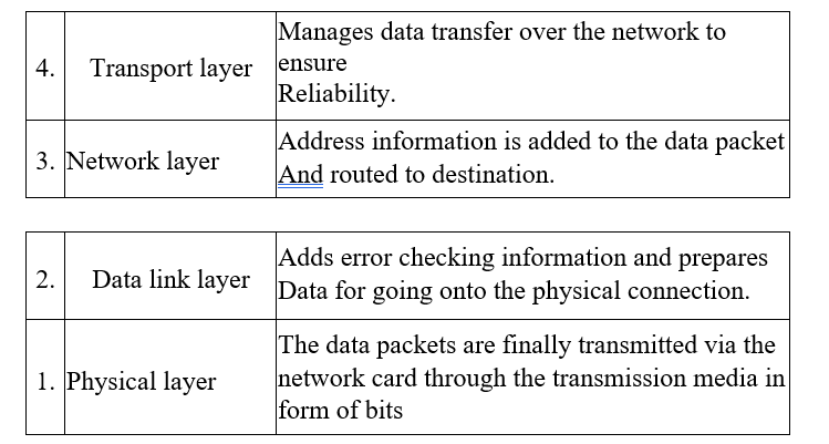
The data transmission process over the network has to be broken down into discrete systematic steps. At each step, a certain action takes place. Each step has its own rules and procedures as defined by the network protocols. The work of these protocols must be co-ordinated so that there are no conflicts or incomplete operations. This co-ordination is achieved through protocol layering. Network protocols are designed after the open systems interconnection (OSI) model. The open systems interconnection model is not a protocol as such but is meant to help designers to come up with high quality layered protocols. It has seven layers, each performing distinct functions as shown in Table 1.2.

Application protocols work at the highest layer of the OSI model. They provide services to application programs. An example of an application program is an e-mail editor program that enables composing or reading of e-mail messages. Examples of protocols at the application layer include:
- Simple mail transfer protocol (SMTP) – An Internet protocol for transferring e-mails.
- File transfer protocol (FTP) – An Internet protocol for file transfer.
- Apple talk and apple share – Apple computers networking protocol suit.
Transport protocols ensure that data is passed between computers more reliably. Some examples include:
- Transmission control protocol (TCP): This is responsible for delivery of sequenced data over the network.
- Sequential packet exchange (SPX): This part of the Novell’s internet work packet exchange/sequential packet exchange (IPX/SPX) for sequenced data.
- NetBEUI: A local area network protocol for Microsoft and 1MB networks that establishes communication sessions between computers.
- Apple transaction protocol (ATP): Apple computer’s communication session and data transport protocol.
Network protocols provide link services. They handle addressing and routing information, error checking and retransmission of requests. Some examples of network layer protocols include:
- Internet protocol (IP): It does packet forwarding and routing.
- Internetwork packets exchange: Netware’s protocol for packet forwarding and routing.
Network topologies
The term network topology refers to the way in which computers and other devices have been arranged or how data is passed from one computer to another in the network. Therefore network topology can be viewed in two ways namely logical and physical topology.
Logical topology
Logical topology also called signal topology deals with the way data passes from one device to the next on the network. Examples of logical topologies are Ethernet and token ring. This means that two networks with different physical layout may have the same logical topology.
Ethernet topology
In Ethernet topology, all computers listen to the network media and can only send data when none of the others is sending.
Token ring topology
In token ring topology, a special package for data called a token goes around the network and only the computer whose address is on the data held in the token will take up the token to read the data then release the token. The token can then be captured by another computer which needs to transmit data.
Physical topology
Physical topology refers to the physical layout or arrangement of components on the network. Examples of physical topologies include star, bus, ring, mesh and tree/hierarchical topology.
Star topology
In star topology, all devices are connected to a central hub. Nodes communicate across the network by passing data through the hub. When the hub receives data from a transmitting computer, it broadcasts the message to all the other nodes on the network. Until recently, the star topology was found mostly in minicomputer and mainframe environments. The topology consists typically of a system of terminals or personal computers, each connected to a central server. The advantages of star topology include:
- It allows centralisation of key networking resources like concentrators and servers.
- It gives the network administrator a focal point for network management. When something goes wrong with the network, the administrator can troubleshoot it from one place, usually a wiring closet, but possibly from a remote management terminal.
- Star networks are easy to configure.
The disadvantages of star topology include:
- The star-based network is costly because it requires one complete cable per computer. Each workstation is connected to the central concentrator by its own dedicated line. In some star-based network technologies this line is coaxial cable that runs from an active hub to a workstation.
- If the central hub fails, the entire network will be down.
- Installing is time consuming because each node forms a segment of its own.
Bus topology
All devices are connected to a central cable called the bus or
backbone as shown in Figure 1.26. The sharing of the transmission media (or bus) has several problems. Most importantly, it means that the cable can carry only one message at a time and each workstation on the network must be capable of knowing when it can and cannot transmit using this shared medium.
A terminator is attached to each end of the cable to avoid signals from bouncing back and forth on the cable causing signal distortion. As the data passes along the cable, each station checks whether the data is addressed to it. If the address matches the machines address, it receives the data otherwise it rejects it. The network addresses of computers on a network are called the medium access control (MAC) address.
The advantages of the bus topology are:
- It is easy to install.
- It is less costly. Does not require a complete cable length per computer. The disadvantages of bus topology are:
- A cable break in any section brings down the whole networks.
- Troubleshooting a cable fault is difficult because the fault could be anywhere on the cable.
- The bus topology limits the number of computers that can be connected to the cable because each computer is listening to the cable in order to transmit. This means that an increase in the number of computers results in an increased collision as machines compete for transmission.
Ring topology
In a ring topology, all devices are connected to one another in the shape of a closed loop each station is responsible for regenerating and retransmitting signals around the network to its neighbour. A token is used to exchange data from one station to another. A token can be viewed as an envelop or a bag where data is placed for transmission and carried around the network.
The advantages of ring topology are:
- They use a short length cable.
- Ring topology is simple to install.
The disadvantages of ring topology are:
- Modification may be difficult because adding or removing a device can disrupt the entire network.
- Troubleshooting can be difficult.
- One device or media breakdown may affect the entire network.
However, this is not the case with IBM token ring where a device called Multi Station Access Unit (MSA U) is used for station bypass in the event a station fails.
Mesh topology
This is the most common type of topology used in wide area network where there are many paths between different locations. Devices are connected with many redundant interconnections between the nodes. In a true mesh topology every node has a connection to every other node in the network. This is a hybrid topology. Groups of star-configured networks are connected to a linear bus backbone
Setting up a peer-to-peer local area network
This practical activity is a step by step guide on how to set up a simple local area network. The following are some of the requirements you need.
Hardware requirements
- A computer running on any version of Microsoft Windows especially Windows 9x / 2000 / ME / Windows XP.
- Network Interface card. Some computers may have it already installed onboard so that you do not have to purchase one.
- A hub or a switch.
- Transmission media preferably unshielded twisted pair category 5. 5. RJ45 connectors.
Tools
- Crimping tool
- Cable tester Screw drivers.
Installing a network card
The network interface card acts as the physical interface or connection between the computer and a properly terminated transmission cable. As mentioned earlier, some motherboards come with on-board network interface cards hence you may not need to plug in a separate add-on card.
To physically install an add-on card:
- Disconnect the computer from the power source.
- Open the system unit and identify an empty expansion slot on the motherboard.
- Insert the card and screw it into place. Some little force may be needed to push the card into place squarely. Make sure that all the conductor points of the card sink into the expansion slot. Avoid touching the golden conductor points and chips on the card with your bare hands.
NB: Some cards are slotted into Industry Standard Architecture (ISA) slots while others are designed for Peripheral Components Interconnect (PCI) slots. Make sure you install in the right slot and then screw into place.
- Replace the casing then connect the computer to the power supply and boot it up. If you are using Microsoft Windows 9x and above, the computer will detect the new hardware because of the plug and play feature found in the operating system. It may install the protocols and device software needed for the proper operation of the network interface card automatically! If there is a problem of the card being detected, you may have to configure the card manually using software on a disk that comes with the card.
Installing the drivers manually
- Click tart, Settings then, ControlPane1. In the Control Panel window double click the Network /Network Connections icon. A dialog box will be displayed. (In some Windows versions you may have to double click the Network and Dial-up Connections icon found in the control panel then double-click the local area connection icon.)
- Click the configure button.
- Click adapter/drivers and then click ADD. Follow the on screen instructions.
Adding protocols
- Make sure the Network dialog box is open.
- Click ADD then protocol
- Click Microsoft, select TCP/IP and NetBEUI from the protocol list then ok
- Click Apply
Identifying your computer in a workgroup
A workgroup is a collection of computers that are on the same network. To specify your computer and the name of the workgroup:
- If you are using Windows 9x, click the identification tab from the Network dialog box. If you are using Windows Me, 2000 or XP. Identification (Computer Name) tab is located in system properties dialog box. Right click My computer, click Properties then click the computer name tab.
- Type your computer name and the workgroup name. The computer name you give must be unique.
Configuring transport control protocol/internet protocol (TCP/IP)
In order to communicate with other computers, you need to install and configure a protocol. In our case let us use TCP/IP. To configure TCP/IP,
- Select the TCP/IP Ethernet adapter from the list titled The following network components are installed/ This connection uses the following items. 2. Click the properties button then the Specify the IP address option,
- Type in the IP address box an address such as 192.168.00.001. Each computer should have a unique IP address. Figure 1.32 shows a TCPI IP properties dialog box in Microsoft Windows XP.
- Specify the subnet mask. Subnet masks are values that allow the router to distinguish the network ID from host ID portions of the IP address. If the IP address is examined by the subnet mask and found to be identical, the message is destined to a host on the same network otherwise it is routed to another network. Typically, subnet masks use the format 255 .x.x.x. In our case let us use a subnet mask such as 255.255.255.0.
- Click APPLY then Ok The computer will prompt you to restart in order for the changes to be effected. 6. Restart the computer
Media preparation and connection
In this practical, we are going to use twisted pair cabling technique because it has become almost the default method. This type of media uses a connector known as RJ45 to terminate the cable. RJ45 is attached to a UTP cable using crimping tool. To attach an RJ45 connector to a UTP cable, proceed as follows:
- Cut a piece of cable of suitable length approximately 3 metres.
- Strip off approximately a dimension centimeter of the cable sheath on both ends to expose the inner pairs.
- Untwist the pairs.
- Using the wiring diagram, place the wires in the correct order and trim the edges to make them even.
Key
- Green striped
- Green
- Orange striped
- Blue
- Blue striped
- Orange
- Brown striped
- Brown
- Insert the wires into the RJ45 connector; plug it in their correct order and then push it into the crimping tool.
- Squeeze the handles of the tool to make sure the wires are pierced and held tightly in the connector.
- Repeat steps 5 and 6 at the other end of the cable. Your cable should now be terminated on both ends
- You can then test the media for continuity and correct termination using the cable tester.
Connecting the computers to the hub/switch
It is now time to connect the computers together through the hub. To connect the computers:
- Connect one end of the cable to the RJ45 port of the network card and the other end to one port in the hub. If the hub is powered, a LED will indicate the connection. Repeat all this process for all other computers that you wish to connect on the network.
- To see if the networking is successful, right click the Network Neighborhood/ My Network Places on the desktop. If all the connected computers in the same workgroup can “see” one another then you have succeeded setting up a peer-to-peer network.
- if not, you may decide to test the connection using the PING For example if you have two computers with the IP addresses 192.168.001.001 and 192.168.001. 028.
To test the connection between the two, proceed as follows:
- From the START, menu of the computer with IP address 192.168.001. 001, choose the RUN menu and type the command PING 192.168.001. 028.
- Click, 0K.A connection failure will be displayed on the screen
Sharing network resources
If you have successfully installed the network, you can then start enjoying the benefits of networking by enabling resource sharing. For example if you are using Windows XP, you can share resources by enabling sharing and security as follows:
- Open Windows Explorer.
- From the explorer window, right click the drive folder or file you wish to share with others on the network then select sharing and security.
- Click the Sharing tab then enable “share this folder“.
- Type in the share name and set other options as required.
- Click 0.K.
Network security
Network security is like the security measures we implement in our homes. You do the best you can to protect yourself from intruders. Likewise in networking you should try to protect your data and information from intruders. In networking there are several ways of enforcing security one of them is share level and the other is the user level security.
Share level security
Share level security is a sample network security used in peer to peer networks. The user can decide which resources to give for sharing. Most desktop operating system such as Window 9X provide such kind of security.
User-level security
User level security model is used on server based networks. A network administrator assigns accounts to users. This means that each user is provided with a unique name and password which he or she can use to access network resources. For more on user level security, read documentations on operating system such as Microsoft Windows NT 4.0/2000/2003, UNIX, Novell Netware, Linux Fedora etc.