

UNIVERSITY EXAMINATIONS: 2014/2015
EXAMINATION FOR THE DIPLOMA IN COMPUTER
MAINTENANCE
DCM 112: ANALOGUE CIRCUITS AND FAULT DIAGNOSIS
DATE: NOVEMBER, 2014 TIME: 1½HOURS
INSTRUCTIONS: Answer any THREE Questions
QUESTION ONE
a) Three resistors namely R1 = 4Ω, R2 = 12Ω and R3 = 8Ω are connected to form a circuit
across and voltage source V = 15V. If R1 is in series with the parallel combination of R2
and R3, calculate
i) The current from the source [3
Marks]
ii) The potential drop (p.d) across R2 [3
Marks]
iii) The current flowing through R3 [2 Marks]
b) With the aid of a labeled diagram, describe the full wave bridge rectifier and clearly
differentiate the negative half cycle from the positive half cycle [8 Marks]
c) Give the units of the following electronic quantities
i) Power
ii) Current
iii) Capacitance
iv) Inductance
[4 Marks]
QUESTION TWO
a) With the aid of a diagram, derive the impedance formula for a series R-L-C circuit
[4 Marks]
b) A circuit having a resistance of 4Ω, an inductance of 0.05H and a capacitance in series is
connected across a 100V, 50Hz supply. Calculate
i) The capacitance to give resonance [4
Marks]
ii) The voltages across the inductance and capacitance [4
Marks]
iii) The Q factor of the circuit [2 Marks]
c) Briefly describe the three bipolar junction transistor configurations [6 Marks]
QUESTION THREE
a) Describe the operation of the following waveform generator circuits
i) CR phase shift [4 Marks]
ii) Hartley [4
Marks]
b) State the purpose and operation of the following voltage regulators
i) Series [4 Marks]
ii) Shunt [4 Marks]
c) Differentiate the triac from the thyristor [4 Marks]
QUESTION FOUR
a) State Kirchoff’svoltage and current laws [4 Marks]
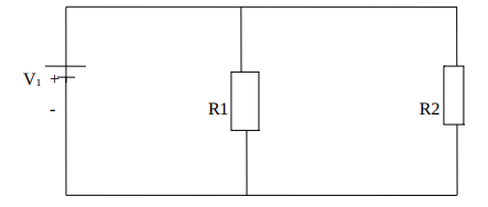
b) For the circuit shown in the figure below where R1 = 10Ω, R2 = 20Ω and V1 = 30V.
Calculate
i) The current through R1
ii) The current through R2
d) For the circuit shown below, calculate the currents shown using superposition theorem
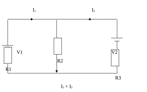
Assume that R1 = 4Ω, R2 = 10Ω, R3 = 8Ω, V1 = 20V and V2 = 15V [8 Marks]
QUESTION FOUR
a) A 5.0V stabilized power supply is required to be produced from a 12V DC power supply
input source. The maximum power rating of the zener diode is 2W. With the aid of a
zener diode regulator circuit calculate
i) The maximum current flowing through the zener diode
ii) The minimum value of the series resistor connected to the diode
iii) The load current if a load resistor of 1kΩ is connected across the zener diode.
iv) The zener current at full load
[8 Marks]
b) Describe the three possible biasing conditions for the standard P-N junction diode
[6 Marks]
c) Draw the symbols for the following electronic devices
i) Operational amplifier
ii) P-N junction diode
iii) N-P-N transistor
3
iv) A.C voltage source
[6
Marks]
4