
Introduction
In Book 1 of this series, we learnt that computers are classified according to functionality, physical size and purpose. We saw that when classified according to functionality, computers can be analog, digital or hybrid. Digital computers process data that is in discrete form while analog computers process data that is continuous in nature. Hybrid computers, on the other hand can process both discrete and continuous data.
In digital computers, the user input is first converted and transmitted as electrical pulses that can be represented by two distinct digits’ l’ and ‘0’ before processing. These two digits are referred to as binary digits or in short bits.
Although two graphs can look different in their appearance, they may repeat themselves at equal time intervals. Electronic signals or waveforms of this nature are said to be periodic. Generally, a periodic wave representing a signal can be described using the following parameters.
- Amplitude (A)
- Frequency (f)
- Periodic time (T)
Amplitude (A): Amplitude is the maximum value a wave can attain. For example, the amplitude of waves in Figure 1.1 is 1.
Frequency (f): Frequency of a wave is the number of cycles made by the wave in one second. It is measured in units called hertz (Hz). 1Hz is equivalent to 1 cycle/second.
Periodic time (T): The time taken by a signal to complete one cycle is called periodic time. Periodic time, T, is given by the formula T = 1/f where f is the frequency of the wave.
When a digital signal is to be sent over analog telephone lines e.g. e-mail, it has to be converted to analog signal. This is done by connecting a device called a modem to the digital computer. This process of converting a digital signal to an analog signal is known as modulation. On the receiving end, the incoming analog signal is converted back to digital form in a process known as demodulation.
Concepts of data representation in digital computers
Since digital computers are the most widely used, this book seeks to explain in details how data is represented in digital form.
Data and instructions cannot be entered and processed directly into computers using human language. Any type of data be it numbers, letters, special symbols, sound or pictures must first be converted into machine readable form i.e. binary form. Due to this reason, it is important to understand how a computer together with its peripheral devices handle data in its electronic circuits, on magnetic media arid in optical devices.
Data representation in electronic circuits
Electronics components, such as the microprocessor, are made up of millions of electronic circuits. The availability of a high voltage (on) in these circuits is interpreted as ‘I’ while a low voltage (off) is interpreted as a ‘0’. This concept can be compared to switching on and off of an electric circuit. (Figure 1.3). When the switch is closed, (Figure 1.3 (a)), the high voltage in the circuit causes the bulb to light (‘ l’ state). On the other hand, when the switch is open (Figure 1.3 (b)), the bulb goes off (‘0’ state).
Data representation on magnetic media
The presence of a magnetic field in one direction on magnetic media is interpreted as ‘I’, while the field in the opposite direction is interpreted as ‘0’. Magnetic technology is mostly used on storage devices which are coated with special magnetic materials such as iron oxide. Data is written on the media by arranging the magnetic dipoles of some iron oxide particles to face in the same direction and some others in the opposite direction. Figure 1.4 shows how data is recorded on the surface of a magnetic disk. Note that the dipoles on the track are arranged in groups facing opposite directions.
Data representation on optical media
In optical devices, the presence of light is interpreted as ‘1’ while its absence is interpreted as ‘0’. Optical devices use this technology to read or store data. Take an example of a CD-ROM. If the shiny surface is placed under a powerful microscope, the surface can be observed to have very tiny holes called pits. The areas that do not have pits are called land (Figure 1.5).
In Figure 1.5 (a) the laser beam reflects from the land which is interpreted as ‘1’ while in Figure 1.5 (b) the laser beam enters a ‘pit’ and is not reflected. This is interpreted as ‘0’. The reflected pattern of light from the rotating disk falls on a receiving photoelectric detector that transforms the patterns into digital form.
Reason for use of binary system in computers
It has proved difficult to develop devices that can understand or process natural language directly due to the complexity of natural languages. It is, however, possible to develop devices that can understand binary language. Devices that read, process and output data in digital form are used in computers and other digital devices such as calculators. Binary logic has therefore simplified the technology needed to develop both hardware and software systems. Other reasons for the use of binary are that digital devices are more reliable, small in size and use less energy as compared to analog devices.
Bits, bytes, nibble and word
The terms bits, bytes, nibble and word are used widely in reference to computer memory and data size. Let us explain each term.
Bits: A bit can be defined as binary digits that can either be 0 or 1. It is the basic unit of data or information in digital computers.
Byte: A group of bits (often 8) used to represent a character is called a byte. A byte is considered as the basic unit of measuring memory size in computers.
A nibble: Half a byte, which is usually a grouping of 4 bits is called a nibble.
Word: Two or more bytes make a word. The term word length is used as a measure of the number of bits in each word. For example a word can have a length of 16 bits, 32 bits, 64 bits etc.
Types of data representation
Computers not only process numbers, letters and special symbols but also complex types of data such as sound and pictures. However these complex types of data take a lot of memory and processor time when coded in binary form. This limitation necessitates the need to develop better ways of handling long streams of binary digits. Higher number systems are used in computing to reduce these streams of binary into manageable form. This helps to improve the processing speed and optimise memory usage.
Number systems and their representation
As far as computers are concerned, number systems can be classified into four major categories:
- Decimal number system.
- Binary number system
- Octal number system.
- Hexadecimal number systems.
Let us now consider each number system and its representation.
Decimal number system
The term decimal is derived from a Latin prefix deci which means ten. Decimal number system has ten digits ranging from 0-9. Because this system has ten digits, it is also called a base ten number system or denary number system,
A decimal number should always be written with a subscript 10 e.g. XIO
But since this is the most widely used number system in the world, the subscript is usually understood and ignored in written work. However, when many number systems are considered together, the subscript must always be put so as to differentiate the number systems.
The magnitude of a number can be considered using three parameters.
- Absolute value.
- Place value or positional value.
- Base value.
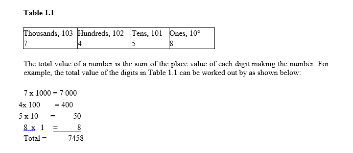
The absolute value is the magnitude of a digit in a number. For example, the digit 5 in 7458 has an absolute value of 5 according to its value in the number line as shown in the Figure 1.6.
The place value of a digit in an number refers to the position of the digit in that number i.e. whether “tens”, “hundreds”, “thousands” etc. as shown in Table 1.1.
The base value of a number also known as the radix, depends on the type of number system that is being used. The value of any number depends on the radix. For example the number 10010 is not equivalent to 1002,
Binary number system
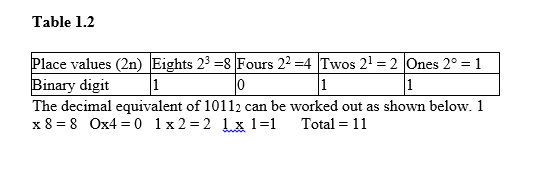
Binary number system uses two digits namely, 1 and 0 to represent numbers. Unlike in decimal numbers where the place values go up in factors of ten, in binary system, the place values increase by factors of two. Binary numbers are written as X2. Consider a binary number such as 10112. The right most digit has a place value of 1 x 2° while the left most has a place value of 1 x 23 as shown in Table 1.2.
Octal number system
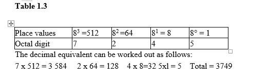
The octal number system consists of eight digits running from 0 – 7. The place value of octal numbers go up in factors of eight from right to left as shown in Table 1.3. For example to represent an octal number such as 724\, we proceed as follows:

Hexadecimal number system
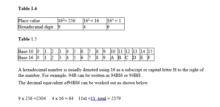
This is a base sixteen number system that consist of sixteen digits ranging from 0 – 9 and letters A – F where A is equivalent to 10, B to 11 up to F which is equivalent to 15 in base ten system. The place value of hexadecimal numbers goes up in factors of sixteen as shown in Table 1.4. Table 1.5 gives digits for base 10 and base 16.
Further conversion of numbers from one number system to another
So far, we have looked at the four types of number systems and introduced their basic concepts in a general and limited way. However, in this section, we shall have a detailed look at how to convert numbers from one system to another. The following conversions will be considered.
- Conversion between binary and decimal numbers.
- Converting octal numbers to decimal and binary form.
- Converting hexadecimal numbers to decimal and binary form.
Conversion between binary and decimal numbers
Converting binary numbers to decimal numbers
To convert a binary number to decimal number, we proceed as follows:
- First write the place values starting from the right hand side.
- Write each digit under its place value.
- Multiply each digit by its corresponding place value.
- Add up the products. The answer will be the decimal number in base 10.
Converting decimal numbers to binary
To convert a decimal number to binary, there are two possible methods, the long division method and the place value method.
In long division method, the decimal number is continuously divided by 2. However, at each level of the division, the remainder which is either a 1 or 0 is written to the right of the quotient. Starting from bottom upwards, read the series of the remainder digits. The series of 1 ‘s and O’s obtained represent the binary equivalent of the number.
To convert a decimal number to a binary number using place value method proceed as follows:
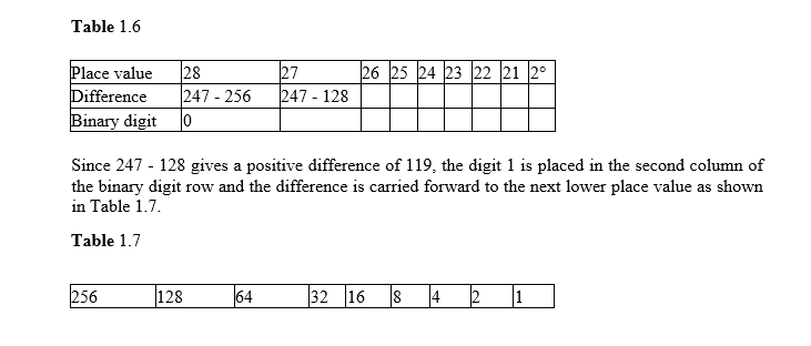
Write down the place values in factors of 2 up to the value immediately larger or equal to the number being considered. For example, to convert 24710 into binary, we write” down the place values up to 28 i.e.256. Similarly to convert 25810‘ write down the place values up to 29 i.e. 512. If the number being considered is itself a factor of 2 such as 64, 128, 256 etc., then place values should be written up to the number itself.
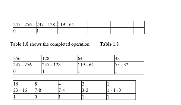
Let us now convert 24710 to binary. Starting from the left as shown in Table 1.6, subtract the place value from the number being converted. If the difference is a positive number or a 0, place a 1 in the binary digit row. If the difference is negative, place a Zero.
In Table 1.6, a 0 is placed in the binary digits row of the first column because 247 – 256 gives a negative value. The number 247 is then carried forward to the next lower place value i.e. 128.
Converting a binary fraction to decimal number
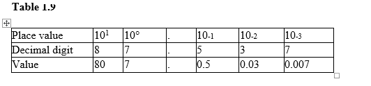
A decimal number which has both an integral and fractional part is called a real number. The weight of the integral part of a real number increases from right to left in factors of I 0 while that of the fractional part decreases from left to right in factors of 10-x. Table 1.9 shows how a real number 87.537 can be represented using the place values.
For a binary number, the same approach as in Table 1.9 can be used, only that the place values (weight) are based on factors of 2. For example, the binary number 11.110112 can be represented as shown in Table 1.10.
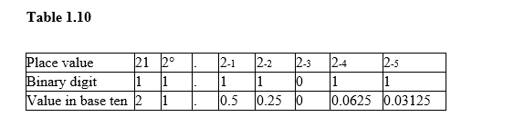
NB: When converting a real number from binary to decimal, work out the integral and fractional parts separately then combine them.
Converting a decimal fraction to binary
Remember that to convert a decimal integer to its binary equivalent we continuously divide the number by 2. In real decimal numbers, we do the same for the integral part. However to convert the fractional part to its binary equivalent, we proceed as follows:
- Multiply the fractional part by 2 and note down the product.
- Take the fractional part of the immediate product and multiply it by 2 again.
- Continue this process until the fractional part of the subsequent product is 0 or starts repeating the value of the original fractional part of the number being converted:
- The binary equivalent of the fractional part is extracted from the products by reading the respective integral digits from the top downwards as shown by the arrow in Combine the two parts together to get the binary equivalent.
Converting octal numbers to decimal and binary numbers
Converting octal numbers to decimal numbers
To convert a base 8 number to its decimal equivalent we use the same method as we did with binary numbers. However, it is important to note that the maximum absolute value of an octal digit is 7. For example 982 is not a valid octal number because digits 8 and 9 are not octal digits, but 7368 is valid because all the digits are in the range of 0 – 7. Example 1.13 and 1.14 show how to convert an octal number to a decimal number.
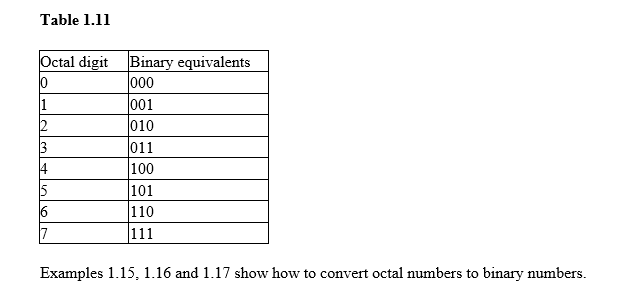
Converting octal numbers to binary numbers
To convert an octal number to binary, each digit is represented by 3 binary digits because the maximum octal digit i.e. 7 can be represented with a maximum of 3 digits. See Table 1.11.
Converting hexadecimal numbers to decimal and binary numbers
Converting hexadecimal numbers to decimal number
To convert a hexadecimal number to its base ten equivalents, we proceed as follows:
- First write the place values starting from the right hand side.
- If a digit is a letter such as an ‘A’ write its decimal equivalent.
- Multiply each hexadecimal digit with its corresponding place value and then add the products.
The following examples illustrate how to convert a hexadecimal number to a decimal number.
Converting hexadecimal numbers into binary numbers
Since F is equivalent to a binary number 11112, the hexadecimal numbers are represented using 4 digits as shown in Table 1.12.
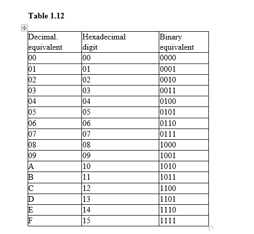
The simplest method of converting a hexadecimal number to binary is to express each hexadecimal digit as a four bit binary number and then arranging the groups according to their corresponding positions as shown in Example 1.21.
Symbolic representation using coding schemes
In computing, a single character such as a letter, a number or a symbol is represented by a group of bits, the number of bits per character depends on the coding scheme used.
The most common coding schemes are the Binary Coded Decimal (BCD), Extended Binary Coded Decimal Interchange Code (EBCDIC) and American Standard Code for Information Interchange (ASCII).
Binary Coded Decimal
Binary Coded Decimal is a 4-bit code used to represent numeric data only. For example, a number like 9 can be represented using Binary Coded Decimal as 10012, Binary Coded Decimal system is mostly used in simple electronic devices like calculators and microwaves. This is because it makes it easier to process and display individual numbers on their Liquid Crystal Display (LCD) screens.
A standard Binary Coded Decimal, an enhanced format of Binary Coded Decimal, is a 6-bit representation scheme which can represent nonnumeric characters. This allows 64 characters to be represented. For example, letter A can be represented as 1100012 using the standard Binary Coded Decimal. A set of Binary Coded Decimal and standard Binary Coded Decimal code are provided in Appendix II.
Extended Binary Coded Decimal Interchange Code (EBCDIC)
Extended Binary Coded Decimal Interchange Code (EBCDIC) is an 8bit character coding scheme used primarily on IBM computers. A total of256 (28) characters can be coded using this scheme. For example, the symbolic representation of letter A using Extended Binary Coded Decimal Interchange Code is 110000012, See Appendix II for a detailed scheme.
American Standard Code for Information Interchange (ASCII)
American Standard Code for Information Interchange (ASCII) is a 7-bit code, which means that only 128 characters i.e. 27 can be represented. However manufacturers have added an eighth bit to this coding scheme, which can now provide for 256 characters. This 8-bit coding scheme is referred to as an 8-bit American Standard Code for Information Interchange. The symbolic representation of letter A using this scheme is 10000012, See Appendix II for more details,
Binary arithmetic operations
In mathematics, the four basic arithmetic operations applied on numbers are addition, subtraction, multiplication and division. In computers the same operations are performed inside the central processing unit by the arithmetic and logic unit (ALU). However the arithmetic and logic unit cannot perform binary subtraction directly. It performs binary subtraction using a process known as complementation. For multiplication and division, the arithmetic and logic unit uses a method called shifting before adding the bits; however, because the treatment of this method is beyond the scope of this book, we shall only explain how the computer performs binary addition and subtraction.
Representation of signed binary numbers
In computer technology there are three common ways of representing a signed binary number.
- Prefixing an extra sign bit to a binary number.
- Using ones complement.
- using twos complement.
Prefixing an extra sign bit to a binary number
In decimal numbers, a signed number has a prefix “+” for a positive number e.g. +2710 and “-” for a negative number e.g. -2710 However in binary, a negative number may be represented by prefixing a digit 1 to the number while a positive number may be represented by prefixing a digit O. For example, the 7-bit binary equivalent of 127 is 11111112, To indicate that it is positive, we add an extra bit (0) to the left of the number i.e. (0) 11111112, To indicate that it is a negative number we add an extra bit (1) i.e. (1) 11111112, The problem of using this method is that the zero can be represented in two ways i.e. (0)00000002 and (1 )00000002,
Ones complement
The term complement refers to a part which together with another makes up a whole. For example in geometry two complementary angles add up to one right angle (90°). The idea of complement is used to address the problem of signed numbers i.e., positive and negative.
In decimal numbers (0 to 9), we talk of nine’s complement. For example the nines complement of 9 is 0 that of 5 is 4 while that of 3 is 6. However, in binary numbers, the ones complement is the bitwise NOT applied to the number. Bitwise NOT is a unary operator (operation on only one operand) that performs logical negation on each bit. For example the bitwise NOT of 11002 is
00112 i.e. Os are negated to Is while I’s are negated to O’s. Likewise the bitwise NOT of 00 1 0
11 0 1 is 110100102 which represents -4510‘ The bitwise NOT of 8-bit zero 000000002 is 111111112, Looking at the two numbers, the most significant digit shows that the number has a sign bit “0” for “+0″ and” 1″ for “-0”. Like in the method of using an extra sign bit, in ones complement, there are two ways of representing a zero.
Twos complement
Twos complement, equivalent to tens complement in decimal numbers, is the most popular way of representing negative numbers in computer systems. The advantages of using this method are:
- There are no two ways of representing a zero, as is the case with the other two methods. 2. Effective addition and subtraction can be done even with numbers that are represented with a sign bit without a need for extra circuitries to examine the sign of an operand.
The twos complement of a number is obtained by getting the ones complement then adding a 1. For example, to get the twos complement of a decimal number 4510‘ first convert it to its binary equivalent then find its ones complement. Add a 1 to the ones complement i.e.
4510 = 001011012
Bitwise NOT (00101101) = 11010010
Two’s complement = 110100112
Binary addition
The five possible additions in binary are:
- 0+0=0 2. 0 + 12= 12
- 12 + 0 = 12
- 12 + 12 =102 (read as 0, carry 1)
- 12 + 12 + 12 = 112 (read as 1, carry 1)
Binary subtraction
Direct subtraction
The four possible subtractions in binary are:
- 0-0=0
- 12-0= 1 3. 12 – 12 = 0
- 102 – 12 = 12 (Borrow 1 from the next most significant digit to make 0 become 102, hence 102 -12 = 12)
The following examples illustrate binary. Subtraction using the direct. method.
Subtraction using ones complements
The main purpose of using the ones complement in computers is to perform binary subtractions. For example to get the difference in 5 – 3, using the ones complement, we proceed as follows: 1. Rewrite the problem as 5 + (-3) to show that the computer performs binary subtraction by adding the binary equivalent of 5 to the ones complement of 3.
2.Convert the absolute value of 3 into 8-bit equivalent i.e. 000000112,
3.Take the ones complement of 000000 112 i.e. 111111002 which is the binary representation of
-310‘
- Add the binary equivalent of5 to the one’s complement of3 i.e.
000000101
+ 111111000
(1)00000001
Looking at the difference of the two binary numbers, you will observe that:
- It has a ninth bit. The ninth bit is known as an overflow
- The result show that the difference between the two numbers is 00000001. This is not true! We know that it should be 00000010.
To address this problem in a system that uses ones complement, the overflow digit is added back to the magnitude of the 8-bit difference. Therefore the difference becomes 00000001 + 1 = 00000010, which is the correct answer.
Subtraction using twos complements
Like in ones complement, the twos complement of a number is obtained by negating a positive number to its negative counterpart. For example to get the difference in 5 – 3, using the two’s complement, we proceed as follows:
- Rewrite the problem as 5 + (-3).
- Convert the absolute value of 3 into 8-bit binary equivalent i.e. 00000011.
- Take the ones complement of 000000 11 i.e. 11111100.
- Add a 1 to the ones complement i.e. 11111100 to get 11111101
- Add the binary equivalent of 5 to the twos complement of 3 i.e.
000000101
+ 111111001
(1 )000000 1 0
Ignoring the overflow bit, the resulting number is 00000010 which is directly read as a binary equivalent of +2.