
DIAGRAMMATIC REPRESENTATION OF DIVISIONS OF A COMPUTER
The following diagram shows the basic physical computer breakdown that will serve as a reference throughout the chapter.
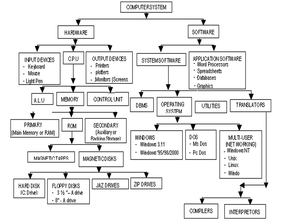
KEY:
C.P.U – Central Processing Unit
A.L.U – Arithmetic Logic Unit
DOS – Disk Operating System
ROM- Read Only Memory
RAM- Random Access Memory
DBMS- Data Base Management System
2.1 DISTINCTION BETWEEN HARDWARE AND SOFTWARE
A Computer hardware from the simplest point of view is the physical or tangible parts of a computer whereas software are the intangible parts that help the computer to do its task. From a technical stand point, the following are the valid definitions and hence the distinction between the two terms.
A hardware is a name that describes all the electronic, electrical and mechanical components of a computer together with its peripheral devices.
A software is the name that describes all the programs that are used to run the computer or do a specific task together with its documentation.
Explanation of the terms
Peripheral devices referred to above are: input devices e.g keyboard, mouse or output devices e.g monitor, printer. These are devices that are used at the periphery or at the side or alongside the computer.
Documentation refers to, in its simplest form, the manual that helps the user to know how the different parts of the software work, how to install it, uninstall, trouble shoot or as a reference book. The definition of software is not complete until documentation is included.
2.2 THE COMPLETE COMPUTER SYSTEM
Because of the recent advances in hardware technology, people have thought of computers as hardware devices only. This is far from the truth. The fact is, the hardware is only one part of the complete system. Without programs to tell the computer what to do, they remain immobile and unproductive, just like an automobile without fuel.
A computer system is therefore defined as a combination of hardware devices and programs assembled to accomplish specific tasks. The broad categories of programs are often employed by computer’s operation. One category of program is known as Operating system. As the name suggests, the operating system controls the basic aspects of the computer’s operation. It is the driver of the computer.
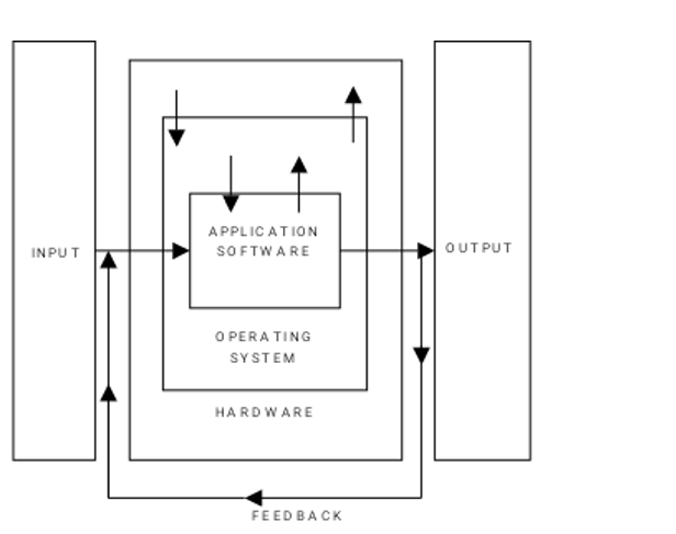
The other category consists of the Application program which instructs the computer to perform those procedures necessary to get some jobs done; for example Word-processing, Accounting programs; as a group are often called Software. Therefore, the three components of a complete computer system are: Hardware, the Operating System and Application Software. The following diagram (fig. 2.3) shows the relationship between these three components.
2.4 ELEMENTS OF A COMPUTER HARDWARE SYSTEM
The hardware components of a computer system consist of a set of interconnected electronic and mechanical devices. All computing machines be it a calculator, a microcomputer or a mainframe has the same parts.
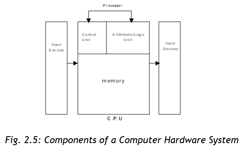
The parts of a hardware system are: Input devices e.g Keyboard, Output devices e.g Monitor, Printer and the Central Processing Unit which comprises of Control Unit (CU) and the Arithmetic Logic Unit (ALU) and Memory.
The figure 2.5 shows the parts of a computer hardware system
2.5 Functional Organization of the Elements of a Computer System
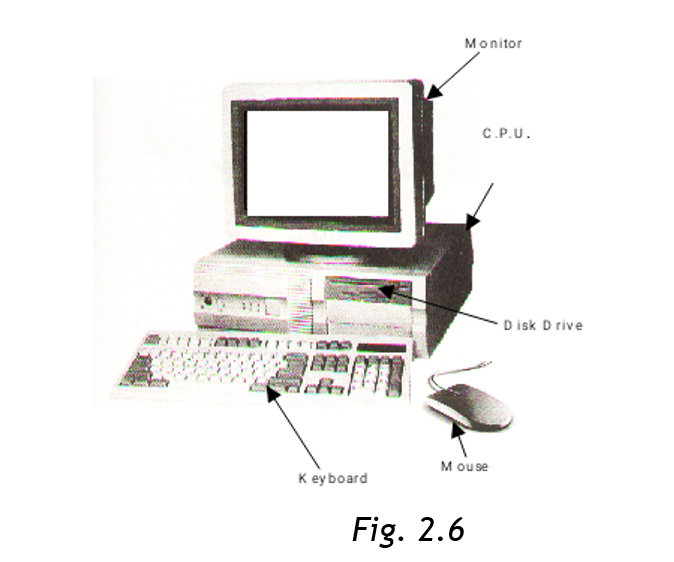
Fig. 2.6 below shows the major physical components of a computer system
2.6 DESCRIPTION OF THE CENTRAL PROCESSING UNIT
The Central Processing Unit is the main component of a computer hardware system. It is usually referred to as the CPU. It consists of three parts. The main part of the CPU is the memory or primary storage, where data being processed and the programs controlling the computer are contained.
Arithmetic Logic Unit forms the second part of the CPU. The ALU performs the calculations and makes comparisons between units of data. The last component is the Control Unit (CU), the work of which is to control the operations of the hardware for example by issuing commands to all elements of the computer as per the dictations of memory. (e.g from the input devices to memory, from memory to output devices, etc).
The Central Processing Unit determines the power of a computer hardware system which is described in terms of :
- Size of Memory, which is measured by the number of characters of data it can store
- Speed of the Control and Arithmetic Logic Unit, which is measured in millions of instructions per second (MIPS).
The work of the various input devices such as terminal keyboard, disk storage units and tape storage units is to send data into the CPU, whereas the work of the output devices such as printers, visual display units, disk and tape units is to give out the results from the processing operations.
The Central Processing Unit also “houses” Registers. The latter is a small part in the CPU that holds data before processing or probably after. They store data to be processed and thereafter partial results. Registers are of different kinds performing different functions:
- Ordinary Counter Register (OC) – This register addresses the next instruction to be expected or we could say it contains the addresses of the next instruction to be
- Instruction Register (IR) – This register contains the actual instruction under
- Accumulator Register – This register stores data to be processed or the results of a partial
The processor communicates with the main memory through 2 registers:
- Memory Address Register (MAR)
- Data Address Register (DAR)
When reading a word from the memory, the CPU stores the address of that word in MAR and sends a read signal to a main memory. After one memory cycle, the value of the word is in DAR from where the CPU will search for it.
When reading a word, the CPU stores in MAR the address of where the write operation will take place. The value to be written will be stored in the DAR and then it sends the write signal to the memory.
Execution of an Instruction
The execution of an instruction of the central processing unit is performed through the following steps:
- Storage of the next instruction to be executed from the main memory to the instruction register (IR);
- Modification of the contents of the OC registers the address of the next instruction;
- Recording of the instruction recently stored;
- Localization of the data needed by the instructions in the memory;
- Storage of data if necessary into the internal registers of the CPU generally the accumulator;
- Execution of the instruction;
- Storage of the results in the appropriate place;
- Return to step (i) for the execution of the next
The Processor
The Control and Arithmetic/Logic Units are usually considered as a hardware device separate from the memory. This is because the size of the memory may vary independently from the Control and Arithmetic/Logic Units. As separate devices they are known as Processor. Processors used in microcomputers are known as microprocessors (refer to chapter 1), but conceptually they are the same processors found in larger computer systems.
Memory
A computer’s memory stores data before, during and after processing as well as the application program in use at the time. These data are stored in cells of the memory. Each memory cell contains one byte of data (a byte = 8 characters: a character is say a letter of the alphabet, or a number). Therefore, one cell will contain eight characters called a byte.
The size of the computer memory is measured in terms of “Kilobytes” or “Megabytes” or “Gigabytes”. Since “Kilo” stands for 1,000 and “Mega” for 1,000,000, computer memory is measured by the thousands or millions of bytes that can be stored in memory at one time.
In computer usage, the prefix “Kilo” actually stands for 1024 bytes and “Mega” for 1,048,576 bytes (explanation later in form 2 – Number systems).
Computer memory is sometimes known as Primary memory Storage, Main Memory and RAM (Random Access Memory).
Primary Memory
Primary storage or RAM is the computer’s working bench. All data to be processed must first be recorded in it and all output of results draws data from it. Primary storage has 2 crucial characteristics. The first is that data can only be stored temporarily, and two, it cannot store a great deal of data.
Secondary Storage
These characteristics of primary storage give rise to the requirements to store large quantities of data in machine readable form that can be fed into RAM in small segments for processing. Units that do this are called secondary storage devices also referred to as Auxiliary Storage or Backing Storage. (Description of these devices latter in the chapter).
The two most prevalent of these are disks and magnetic tapes. These media offer the ability to store data off line, meaning that data can be processed from time to time by the computer system and are not stored permanently as part of the hardware configuration. When needed, they are mounted on data reading and writing device, called drops, as required by their application programs.
- The processor receives data from main storage, performs operations on them, then the result is given back to the
- Data then goes to the main memory comes from input devices or secondary devices, and data from the main memory goes to backing storage or output devices.
- The ALU and CU combine to form the processor as
2.7 DESCRIPTION OF TYPES OF INPUT DEVICES
Input devices in whatever form as the name suggests are devices that help the user to communicate with the computer by issuing commands in different ways which the computer obeys.
2.7.1 Keyboard
Please refer to 1.4 for full keyboard explanations. Using the keyboard is a matter of knowing which command you want to issue to the machine or what entries in the form of characters you want to make; then simply type in the right characters from the keys of the keyboard.
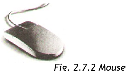
2.7.2 Mouse
This is another type of input device but as opposed to the keyboard, it doesn’t have keys. A mouse has usually two buttons (but not always). When installed in your machine, a pointer is always seen on the screen. Underneath the mouse is a rotating ball which with the slight movement of the device on a pad, the pointer will correspondingly move on the screen by the same distance and to the right direction. To issue an instruction to the system, the user simply needs to click (press the mouse button once – usually the left) a menu and choose a command he wishes to issue or click a command he would want to use. You can use a mouse also to draw different shapes of your style apart from simply clicking commands. A mouse (mice – plural) is usually employed in Windows Applications without which the Windows Operating System become incomplete.
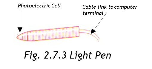
2.73 Light Pens
Looks like an ordinary pen but its tip is a light sensitive detector. When you touch the tip of the pen to the display screen, the computer locates what are called the x-y -ray coordinates of that point. By touching the screen at various points, or by moving the pen across the surface of the screen, you can write and draw.
Normally used with palm tops. Since palm tops are very small light pens replace mouse.
2.74 Joy Stick
This is a device that permits you to move a picture, line, word, or cursor from point to point in a display screen. Used normally in playing computer games.

You operate a joystick by moving it in various directions. It caries out the same functions as the locate keys (cursor control) on the keyboard. But it is faster and lets you move in 8 directions instead of four.
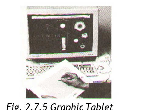
2.7.5 Graphic Tablet
It lets you draw a design just as you might do on paper. You use a special pen or your finger to do the drawing on a flat, table like surface. Your drawing appears immediately on the display screen.
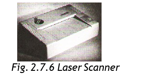
2.76 Laser Scanner
This input device is used to scan a picture or other documents from print onto the screen and hence can be available for storage in the computer memory for processing or future reference. Some printers come with inbuilt scanners. However, we have small scanners (manual) that are held in the hand while scanning an object to the monitor into the memory. You can scan for example your photograph, signature, and logo on other documents. Another scanner is known as flat bed which is used by placing the document to be scanned on it.
2.7.7 Voice Input
Voice input systems require that the user pronounce the vocabulary of voice command several times while the system does the “listening” and analyses the voice patterns of the various words. After this, using an airplay of the voice patterns, the system will respond to the commands as dictated. Once the computer has been initialized with the voice pattern of the person, such system will always not respond to anyone else. Example is voice dialing in a mobile phone.
2.7.8 Voice Input
Voice input systems require that the user pronounce the vocabulary of voice command several times while the system does the “listening” and analyses the voice patterns of the various words. After this, using an airplay of the voice patterns, the system will respond to the commands as dictated. Once the computer has been initialized with the voice pattern of the person, such system will always not respond to anyone else. Example is voice dialing in a mobile phone.
2.7.9 Optical Character Reader (OCR)
This device along with others to be discussed shortly after, have been developed to make data input to computer systems independent of any human operations. Optical Character Readers (OCR) accept data input optically or with machines that respond to magnetic ink or magnetic Ink Character Reader (MICR).
2.7.10 Optical Mark Readers (OMR)
This device will place marks placed on forms for data gathering purposes. Such marks will then be translated into the computer by the device as input data.
2.7.11 Bar Code Readers (or Line Code Readers)
Bar Code Readers will read price and inventory codes printed on products that are frequently purchased such as in supermarkets. This code is usually referred to as Universal Product Code (UPC). Such Bar Code Readers employed in supermarkets are one type of remote date entry terminals. They are known as Point-Of-Sale (POS) terminals. Remote data
entry terminals promote entry of data directly into the computer system for the purpose of updating, inventing files and preparing customer’s bills and other similar tasks. They are often used in manufacturing and distribution in warehouses, retail stores, bank teller counters and other business offices. Workers and executors in the field usually use portable data entry terminal to enter and retrieve data directly into and from the main computer control via telephone lines.
2.7.8 Key to Tape / Key to Disk
This is a system of data entry normally employed when processing spiral documents usually in batches. In any key to disk system, there must be a microcomputer that is used as the processing computer or server. There will be a special computer terminals, each with a different operator in front of it. Provision for a fixed disk drive where data is stored when keyed in is made, and finally there is a tape drive where after completing a given batch of data, then you re-locate. One of the terminals is usually dedicated for a supervisor to the system that oversees the whole operation.
2.7.9 Key to Disk Operation
Each operator loads the program usually employed to enable data entry of batches., then keys in the data from the original documents usually source documents. The program in use will validate the data entry and incase of any error; this will be given on the screen and then will enable the operator to correct. Once this is corrected, the data is stored on disk and the second operator is given the same source document to verify using the same process to the terminal and program. Once a batch is verified as compact, the data is transferred from the disk to the tape drive and finally physically transferred to the server (minicomputer) for processing.
DESCRIPTION OF TYPES OF OUTPUT DEVICES
There are several output devices that are available within the current technological advancement. For our level, we will limit ourselves to the following: Printers, Monitors, Plotters, Sound Output and Microfiche /Microfilm devices.
2.7.10 Printers
Printers are necessary when hard copies of displayed work on the monitor have to be sent to customers, report prepared by the Management and the Board of Directors and so on must be printed. It’s not disputable the fact that other electronic means of transmitting information are now available. Printed-paper, however, still remains the most popular means of communicating the same information. Printers fall into three main categories classified by the amount of printed work the device is able to produce in one operation.
1. Page Printers
These printers print a whole page at once. They are sometimes known as image printers. They produce the images by laser or electrostatic means. The quality of output from such printers is sufficiently high for business correspondence. They use toners just like a photocopy.
2. Line Printers
These type of printers produce a whole line of a text at ago. They are very fast but the quality of the output is always low.
It is important to note that the length of a line is not standard as it differs with the requirement of the application in use. However, most of the printers will print between 120 and 144characters per line. This will require approximately paper width of about 14 inches so as to accommodate the said character scale. 132 characters are often the most common width. These use cartridges.
3. Character Printers
Form or print one character as a time on the paper. This rate of printing varies between 20 and 600 characters per second depending on the mechanism or use in the different makes employed. These printers make use of ribbons.
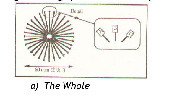
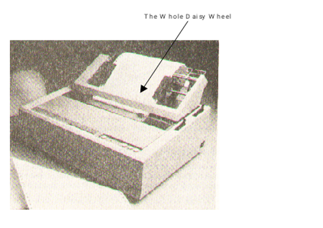
There are many different types of character printers. The first is called Daisy Wheel Printer, which creates fully formed letters much like a typewriter sometimes called Letter Quality Printer. The output is often good enough for business correspondence.
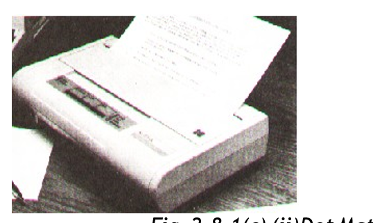
The second is Dot Matrix Printer, which creates characters as spools of dots in a rectangular matrix. The speed of the dot matrix printer is much higher than that of a daisy wheel but the quality of the former is not sufficient enough for business correspondence. A dot matrix printer has a print head consisting of a number of small pins between 9 and 24 depending on the make. A printer with a 9 pin print will give a poor quality print compared to that of a 24 pin print head since the dots in the former are widely spaced apart. If a dot matrix is to produce a better quality output, sometimes referred to as Near Letter Quality (NLQ), then a line is printed twice with the print head being moved along very slightly in the second printing so that those moved spaces between the dots are filled into ensure continuity. One advantage with the dot matrix printers is that they can print from either side, meaning the print head does not have to move say to the left side of the paper in order to begin printing but begin from the right as well. With the dot matrix printer you simply need to change the ribbon of different colour to get a colored output.
How Character printer operates:
A paper is passed through a printer that has a moving belt or a chain containing a complete character set – as seen from the keyboard. A paper is then hit from behind by a set of hammers, which are aligned for each printing position on the line. This will then pass a paper against an inked ribbon behind which is the character to be printed.
Another way to categorize printers is by whether or not the print head strikes the paper. If it does, it is called Impact Printer and if it does not it is called a Non-Impact Printer. Dot matrix and Daisy wheel printers fall in the former category; all strike the paper while printing.
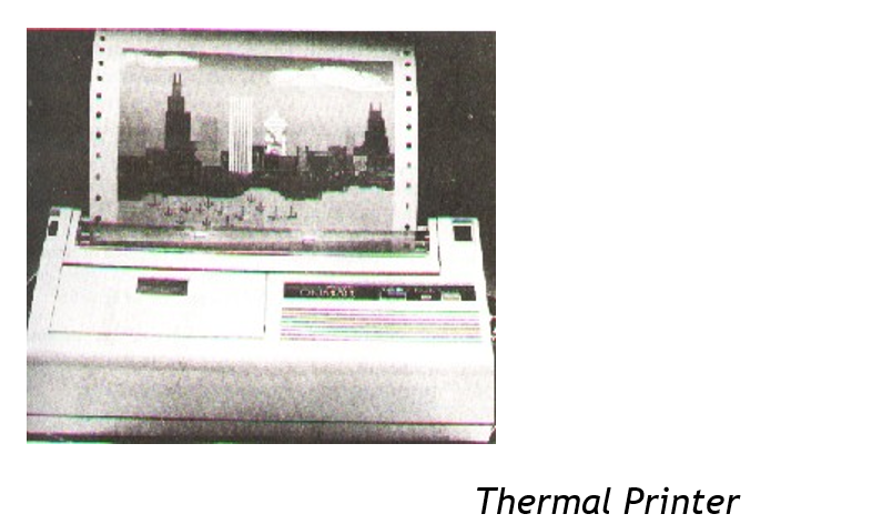
Non-impact printers are usually the fastest since they minimize the amount of physical movement required during the printing process. Examples of non-impact printers include Thermal Printers, Inkjet and Electrostatic Printers.
Impact Printers are usually noisy given the physical motion involved during the printing process when the printing device strikes the paper. To get multiple copies from impact printers, all you need to do is interlace a carbon paper between the papers.
How Non-Impact Printers work
- Thermal Printers
The slowest of all non-impact printers, form characters by burning them on specially treated paper. They operate at about 30 characters per second.
2. Electrostatic Printers
They form characters by charging the paper electrically. The paper is then passed through a toner solution. Particles of the toner solution (ink) stick to the electrically charged areas of the paper. When the paper is heated, the particles melt thus producing the characters. They are quite fast; some print about 300 pages per minute.
Ink Jet Printers
These printers “spit” streams of ink to the surface of the paper. The ink then drips almost immediately. They are fairly slow. They produce from about 50 to 100 characters per second. These printers offset their relative disadvantage of slowness by their low cost and multiple colour printing.
2.8.8 Voice Output
Computer voice output is common place. For example a computer could be programmed to offer telephone information service, like directory help. Others let you know if you dialed a wrong number or if the number you are calling is out of order or busy and the like.
2.8.9 Plotter
This is an output device used to produce graphical output like drawing graphs, charts, maps or electric circuits. The design of the graph, circuit is done on the computer then the output is sent to the plotter. Plotters are of two types: one that has a single sheet sometimes called Flat Set Plotter and the second uses a continuous sheet which rolls continuously on drum like cylinders: also known as Drum Plotters.
2.8.10 Microfiche/Microfilm
Microfiche and Microfilm are both better known collectively as microform. The later is a document photographed and hence stored in a film. Microfiche is a sheet of film that measures 105mm x 148mm whereas a microfilm is actually a 16mm roll film. A typical 16mm will hold the equivalent of 3,000 A4 Pages. One typical microfiche will hold the equivalent of about 98 A4 Pages.
Usually this technique of giving output to a microfilm/microfiche or microform is usually referred to as COM (Computer Output to a Microform). The technique is simple, a machine called a microfilm Recorder reads output that is relayed onto a magnetic tape for the computer, once read, the output is copied out on microfilm/microfiche. The application of COM is suitable where an organization has to store data over a long period of time or where backup copies need to be made. Records that need to be out a long time would include: receipts and invoices of an organization or say catalogues in a library or a bookstore.
2.9 DESCRIPTION OF SECONDARY STORAGE DEVICES AND MEDIA
As mentioned earlier, secondary storage or backing storage provide supplementary memory to main memory of the computer. The following auxiliary media and devices will be discussed: Magnetic tape Drive and Magnetic Tape, Magnetic Disk Drive and Magnetic Disc, Magnetic Diskette Unit and Magnetic Diskette, Optical Disk Unit and Optical Disk, Mass Storage Devices and Media.
2.9.1 Magnetic Tape Drive and Magnetic Tape
The concept of storage in magnetic tape device used by computers is identical to tapes you may have in your home video or audiotapes recorder. As a matter of fact, most microcomputers can use exactly these devices to store data. Magnetic tape consists of a large strip of plastic that has been coated with iron oxide compound that can be magnetized. This strip is typically wound on a 10½ inch for mainframe and microcomputer applications. Microcomputers employ audiotape cassettes. Data is recorded on and read from the tape using a tape drive. The latter has a “read head” for reading the information stored on the tape that’s for transforming data from the tape into main memory. It also has a “write head” for recording the information. Usually, to read from, write to an individual tape, you have to mount it on a tape drive.
In processing data is read from the tape into main memory (or RAM) where processing takes place. The results are given out only as a written report or as another tape file written on another drive. Because RAM capacity is limited, only a small amount of data is used for the input tape or written to the output device at one time.
Data that is stored on magnetic tape as well as other auxiliary storage devices are usually organized into records. A record for now should be understood as a unit of data consisting of characters about someone or something. How data processing uses records is a matter of loading one or more records into RAM for an output device. Processing those records and sending the result to an output device.
This technique of sorting records on tape in the form of groups that are read into or written from RAM all at once giving rise to a number of technical terms that are used in all types of secondary storage media. See fig. 2.9.1 below.
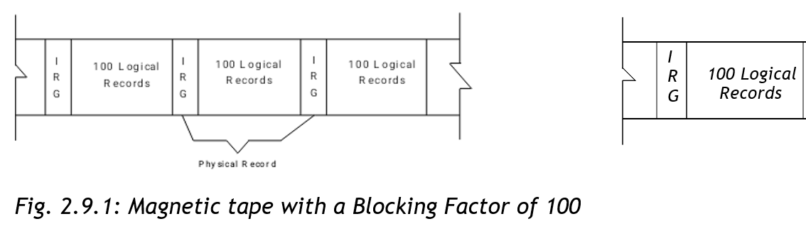
A group of records is called Physical Records or Block. Each record in the group is known as a Logical Record. The number of logical records in a physical record is referred to as the Blocking Factor. A blocking factor of ten will indicate that ten logical records make up one physical record or block. The term block refers to a group of logical records, all of which are read onto or written from RAM at once. The physical records, or block, are suspended from each other by blank spaces on the tape known as Inter- record Gap (IRG). Sometimes known as Interlock Gap.
Magnetic tape is a sequential medium, this means that records appear on it in sequential order for example personal records will appear by: employee number, account number and so on. Because data is stored on tape sequentially, they must also be processed sequentially. If a tape file has only 60,000 records, access to record number 50,747 can be had only by reading through all of the proceeding 50,746 records. This is usually a very slow way of accessing data.
2.9.2 Magnetic Disk Drive and Magnetic Disk
Magnetic disk storage is the preferred medium for most secondary data storage today. As opposed to magnetic tape files, disk files need not be processed sequentially, although they may be if the application calls for it. Any record stored on disk may be retrieved without having top process through all of the proceeding records on the file. For this reason, a disk is usually referred to a Direct Access Storage Device (DASD). This factor is what makes a magnetic disk faster and more flexible than the tape.
Physically a magnetic tape consists of circular platters of non- magnetic such as aluminium and plastic, which is combined with the same sort of non-oxide coating used on magnetic tape. As with, characters are recorded by magnetizing microscopic magnetic fluids on the disk surface using the usual data coding schemes. Magnetization in one direction represents a zero in the other direction a one.
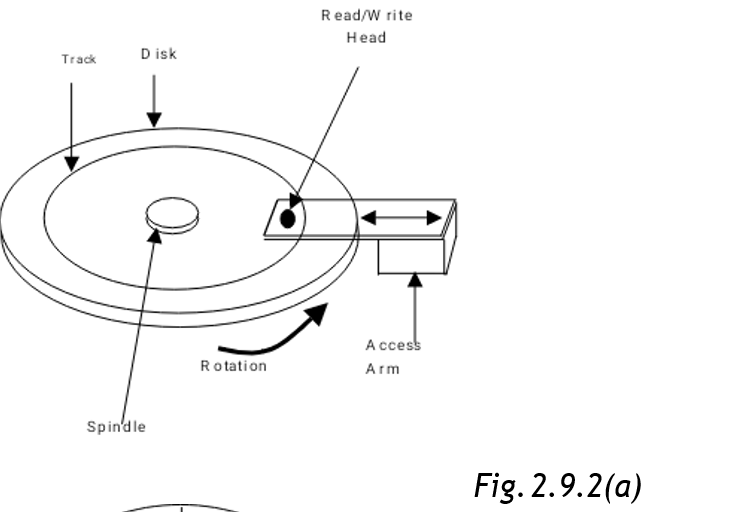
To use a disk one has to mount it on a spindle that causes it to rotate. A read/write head, similar to that of magnetic tape, moves back and forth across the disk radius rotating and storing data as required. The read/write head can move to different sections of a record without necessarily having to write or read this section; only when the instruction was prompted!
Disk Drive is the device on which the disk is mounted when used to store and retrieve data. The device can position the read/write head in a number of portions along the disk radius. As the disk rotates past the read/write head, data is recorded in a circular track. This means therefore, that there are as many concentric tracks displayed on the surface of the disk, as there are positions for read/write head. This is illustrated in Fig. 2.9.2 (a)
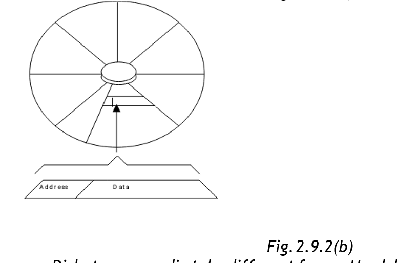
Each track is divided into sections or blocks, similar to the blocks of data in magnetic tape. Each sector has an address. To store/retrieve data, the system finds the disk address used to contain data by moving the read/write head to the appropriate track where it waits until the desired sector passes by.
Fig. 2.9.2 (b) shows how a track is divided into sectors and how the sector contains an address used to locate where data is stored on the disk. A hard disk with a capacity of 300k for example contains forty tracks (40) of nine sectors each; having a total of 360 sectors available on each side; of a two-sided disk for a total of 720 sectors. Each sector contains 512 bytes or 4096 (512 x 8)characters, so the disk offers a total data storage capacity of 368,649-bytes. Such a disk is said to be a 360k disk following the conception that “k” equals 1,024 (360 x 1024= 368640).
Disk storage media take different forms. Hard disks are rigid in nature. They contain the most data. Hard disks may be fixed in their devices or may be removed. They are usually 14” in diameter, although it is unusual to the smaller had disks in microcomputers. One such system is known as Winchester, so named because its prototype makes use of two drops of thirty million bytes each has effectively the “30-30”. It uses a 14” plotter. Later versions called Mini-Winchester or Mini-winns” used 8” or 6” and one-quarter inch plotters, which are stored in the drives and can store up to 85,000,000 bytes.
2.9.3 Magnetic Diskette Unit and Magnetic Diskette
This is another form of disk storage media. Flexible disks or simply diskettes often called floppy disks or floppies because they use a thin sheet of plastic as their case. They are an important data storage medium for micro and mini computers.
Diskettes range in size from 3 ½” to 8”. They offer the advantages of ease of transport and low cost. They are encased permanently in a protective envelope, which is insulated in the disk drive. The entrance to the drive is a narrow slot in front of the drive. This slot has a small flap over it, which must be clipped shut once the disk is inserted.
2.9.4 Optical Disk Unit and Optical Disk
Optical disk is a kin to audio compact disk or CD that you might have in your home. The device is made of plastic cover, which has transparent material. The principle of work is the same as that of the CD; sound is recorded in them in digital form.
Data is recorded beneath the transparent layer that cover the surface of the CD by burning a permanent pattern into the surface of the disk by means of a laser beam. Reading the data is also by a laser beam in an optical disk recorder.
The capacity of a CD is usually about (600 – 750MB). 1 Gigabyte, which is made up of 40,000 tracts each divided into 25 sectors. 1 GB is equal to 1 million characters-(1 GB).
One advantage of CDs to magnetic disks is that loosing of data is not as rampant as with the latter. One disadvantage is that some (i.e CD-R) CDs are not reusable. They are usually referred to as WORM, which stands for Write Once Read Many times. Reading from the CDs tends to be slower than that of the magnetic disks. However, with the advert of CD-RW (Re-writable CDs) you can use a CD writer to delete obsolete work and write new data.
2.9.5 Mass Storage Media
A great need for machine-readable data storage in industries has prompted computer equipment manufacturers to develop storage devices with even higher capacities. The top of the time disk unit manufactured by IBM doe example, stores more than 2.5 billion bytes of data. Data Car-tridge System store data in series of 50 MB cartridges. These devices provide up to half a million bytes of on line storage.
The operation is similar to that of other secondary storage devices. A cartridge is loaded into the read/write mechanism, the data is processed and then the cartridge is replaced in its honeycomb-the storage bin. Then the read/write mechanism moves onto find the next catalogue to be processed. Cartridge systems are slower than disk systems because they involve more physical movements.
2.10 SYSTEM SOFTWARE AND APPLICATION SOFTWARE
2.10.1 System Software
System Software are programs with their associated documentations that control the entire operation of the computer. It is what tells the computer what to do when you issue a command or when you switch on the computer. Within the set of system software, we find a set of programs called Operating Systems. The latter is usually defined as a set of programs that standardize the way a computer’s resources are made available to the user and to applications software. The resources here refer to the hardware components of the computer.
The system software command imprinted on a type of memory called ROM (Read Only Memory). Such memories are usually reserved for such data of the operating system that the user must not modify or inadvertently delete. It is usually protected by the manner in which it is manufactured. ROM is used to store programs and data that are essential for the proper operation of the computer system and of the application program that are integral parts of the operation. ROM is non – volatile; this means whatever is stored in such memory remains whether or not the power is on. (RAM – discussed earlier is volatile). Programs such as operating systems and application programs stored in ROM are often called Firmware, meaning software that is engrained / fixed into the hardware.
System software also has what we refer to as Utility Programs for File management, editing files, management of disks and so on. These are commands resident in system software.
2.10.2 Application Software
This is a program that is usually applied on one area of operation only
– not as all encompassing as system software. Application software is usually divided into 2 categories:
Standard Packages or Application Packages (General Application Software)
These are packages that are designed to be used to solve a particular type of problem for example Lotus 123, Ms Excel are all spreadsheet packages meant to be applied in accounting operation only. Word perfect, Ms-Word are all word processors. D-base 4, Ms Access are database packages and so on.
User Developed Software (or Specialist Application Packages)
These are suites of programs with their associated documentation that are tailor made to solve specific tasks only. Usually, a user will give a specification to a programmer of the suite he wants to be developed to meet his business or individual needs. This kind of software is only restricted to solving problems to which it is programmed to solve. Tailor made software is sometimes known as Bespoke Packages.
SUMMARY
- Computer Hardware is defined as all the electrical, electronic and mechanical components of the computer together with their devices used at the peripheral.
- Software are programs that are used to run the computer together with the associated documentation.
- Computer hardware comprises of Input devices, Output devices and the Central Processing Unit.
- A complete computer system comprises the operating system, system software, application program and hardware.
- CPU is consisted of Arithmetic and Logic Unit which performs arithmetic and logic comparisons, the control unit which coordinates the activities of the hardware (I/O operations) as per the dictates of the memory, memory which stores data being processed, results and the application in use, registers which are slam areas in the CPU that holds data before processing and probably after.
- Storage Devices are in two forms: Primary Storage devices, the Main Memory and Secondary Storage devices which supplements the main memory.
- Input devices include: Keyboard, mouse, paper scanner and magnetic ink holder. Other data capture methods include: speech, magnetic, optical character readers and optical mark reader.
- Output devices include: Printers – which could be line, page or character printers, they are also categorized by whether the print head strikes the paper while printing – impact and non-impact printers, visual display Unit, (or monitor) – displays the text/graphics for the user to see and plotters for plotting graphical output, electric circuits, charts etc.
- Secondary storage media and devices include: Magnetic tapes and disks, optical disks and mass storage media.
- System software are programs that control the entire operation of the computer together with the associated documentation. An application program is software that is usually applied on one area of operations only. They could be standard packages or user developed packages.