

UNIVERSITY EXAMINATIONS: 2019/2020
EXAMINATION FOR THE BACHELOR OF SCIENCE DEGREES IN APPLIED
COMPUTING
BAC 3209 – EMBEDDED SYSTEMS
FULL TIME/PART TIME
ORDINARY EXAMINATIONS
DATE: MAY, 2020 TIME: 6 HOURS
INSTRUCTIONS: Answer ALL Questions
SECTION B: [20 MARKS]
a) The below diagram relates to the minimum inter-event separation time. Use the diagram to answer
the below questions. Note that time answers should be given in ms without the units, example 500.
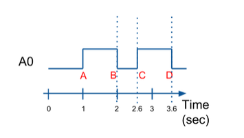
i) How many events are depicted in the above diagram? [2 Marks]
4 The 4 events appear at about 1, 2, 2.6, and 3.6 seconds
ii) What is the separation time between events A and B? [2 Marks]
1000 Event A occurs at 1 second. Event B occurs at 2 seconds. The
separation time between events A and B is 1 second, or 1000 ms.
iii) What is the separation time between events B and C? [2 Marks]
600 The time from 2 sec to 2.6 sec is 600 ms.
iv) What is the minimum inter-event separation time in the entire diagram?
[2 Marks]
600: Events B and C have the smallest separation time between them at 600
ms.
v) In a particular system, a button press less than 300 ms can be ignored. Any
release duration less than 200 ms can be ignored (so treated as a steady longer
press). What is the minimum inter-event separation time? [2 Marks]
200: 200 ms or more separates a falling event and rising event. 300 ms or
more separates a rising event and falling event. 200 ms is the minimum.
vi) If the minimum interevent separation time for a system is 500 ms, what is the
largest period (rounded to a whole number) that will not miss events?
[2 Marks]
If the period is less than 500 ms, no events separated by at least 500 ms will
be missed. Of course, an even shorter period, such as 450 ms, would be
safer.
b) An embedded system uses one custom LCD to display the current time and temperature. The
application runs one thread to manage the temperature sensor and display any temperature change
on the LCD. A second thread reads and displays the current time in minutes. The programmer used
no synchronization whatsoever since the processes monitor different hardware (temp sensor and
clock) for changes. But sometimes the LCD gets garbled up and displays all wrong values. (The
programmer believes this is a hardware glitch since the time correct itself within a minute, and the
temperature just by touching the sensor) Describe the most likely software error causing the error
and how to fix it. [4 Marks]
c) Consider the question of development methodology for embedded systems.
i. Explain why using a development methodology is important. [1 Mark]
ii. Give a compelling reason when you would use successive refinement model and a
compelling reason when you would avoid successive refinement model. [2 Marks]
iii. Give two examples of a development methodology other than successive refinement.
[1 Marks]
SECTION C: [20 MARKS]
a) Consider a system that periodically reads the input from an accelerometer unit. The data
from the accelerometer comes in the following format: X acceleration (2 bytes), Y
acceleration (2 bytes), Z acceleration (2 bytes). The data is provided in big-endian order
whereas the processor uses little-endian. Provide C-like pseudocode for a program that
prints out the acceleration of the three dimensions, read from a 6-byte array buffer
[5 Marks]
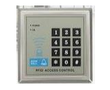
b) An electronic lock controlling entry to a door is one example of an embedded system. See
the figure below with keys labeled 0 to 9. We’re going to take a simpler keypad comprising
just two keys, “0” and “1”. The binary keypad provides inputs S to the Finite State
Machine (FSM) which must decide whether the correct input sequence of 0s and 1s has
been entered. You are told that the entry code is the 4-bit sequence “0110”. If this sequence
has been correctly input to the FSM, then the FSM moves into its end-state where it outputs
a “1” (i.e., the “open” command) to the release mechanism. Any incorrect sequence outputs
a “0” which means “do not open”.
c) A partial Moore Finite State Machine is shown in the figure below. It shows all the states
but only some of the transitions. You should complete the FSM.
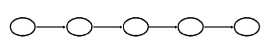
i. Draw all the transitions and label them with the proper inputs [5 Marks]
ii. Mark the initial and the final states [1 Mark]
iii. Write the output in each state. [1 Mark]
d) Consider the following schematic diagram for a serial communication
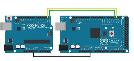
Two Arduino boards are used. The Arduino Uno on the left is the sender and the Arduino
Mega on the right is the receiver. We use the Mega to make it easier to display debugging
information on the computer. The Arduinos are connected together using digitals 0 and 1 (RX
and TX) on the Uno and digitals 16 and 17 (RX2 and TX2) on Mega. The receiver on one
needs to be connected to the transmit on the other and vice versa. The Arduinos also need to
have a common reference between the two, this is done by running a ground wire. The first
step in creating a serial communication system is to package the string to be communicated. In
general a packet is comprised of some start byte, a payload (the data you wish to send), and a
checksum to validate your data. Here, the packet is: [0x53] +[counter value]+[static value]+
[checksum]. The sender code is shown below that increments our counter and send our packet.
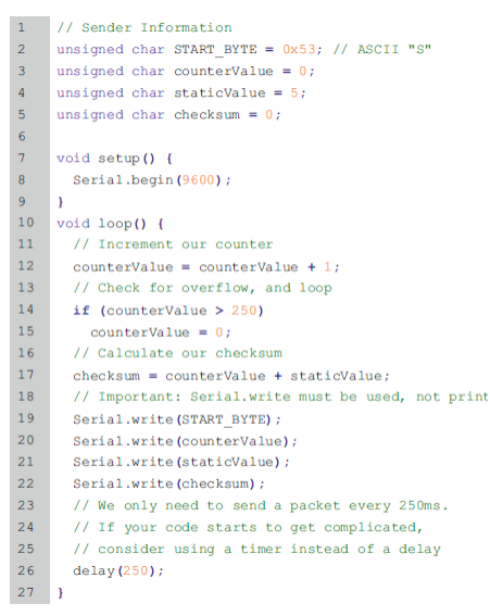
Write the Receiver code for the above send information. [8 Marks]