

UNIVERSITY EXAMINATIONS: 2020/2021
EXAMINATION FOR BACHELORS DEGREE IN APPLIED
COMPUTING/SOFTWARE DEVELOPMENT
BAC 3203/ BSD 3205: EMBEDDED SYSTEMS
INSTRUCTIONS: Question ONE IS COMPULSORY, choose TWO OTHER questions
QUESTION ONE (20 MARKS) COMPULSORY
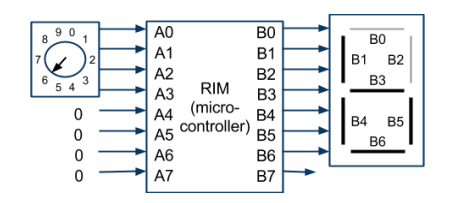
a) Consider the following embedded system with a dial that can set A3..A0 to binary 0 to 9,
and a 7-segment display (Wikipedia: 7-Segment Display) connected to B6..B0 as shown:
Below is a (partial) RIM C program that appropriately sets the display for the given dial
position:
#include “RIMS.h”
void main()
{
while (1) {
switch( A )
{
case 0 : B = 0x77; break; // 0111 0111 (0)
case 1 : B = 0x24; break; // 0010 0100 (1)
case 2 : B = 0x5D; break; // 0101 1101 (2)
//…
case 9 : B = 0x6F; break; // 0110 1111 (9)
default: B = 0x5B; break; // 0101 1011 (E for Error)
}
}
}
i) What B_ outputs should be set to 1 for case 3? List in ascending order separated
by spaces, e.g., B0 B2 … [5 marks]
ii) To what should B be set for case 3? B = ____; Use uppercase letters for the hex
literal. [5 marks]
b) State and explain the results of the following bitwise operation. [10 marks]
i) 00001111 & 10101010
ii) 00001111 | 10101010
iii) 00001111 ^ 10101010
iv) ~00001111
v) Give a statement that sets B’s bits to the opposite of A’s bits, so if A is
11110000, B will be 00001111. End with ;
QUESTION TW0 (15 MARKS)
A parking lot has eight parking spaces, each with a sensor connected to input A. Write a
program that sets B to the number of occupied spaces, by counting the number of 1s
using the GetBit() function. [15 marks]
QESTION THREE (15 MARKS)
Given the following timing diagram and the light on/off SM, determine the value of B0 at
the specified times. [15 marks]
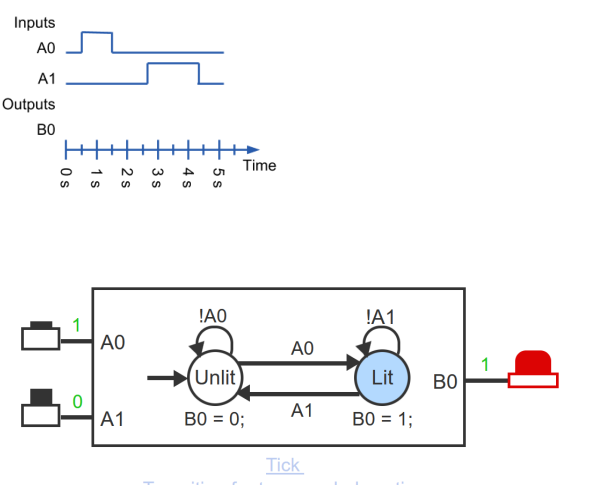
i) 0 s [3 marks]
ii) 1 s [3 marks]
iii) 2 s [3 marks]
iv) 3 s [3 marks]
v) 4 s [3 marks]
QUESTION FOUR (15 marks)
a) Explain and give an example of an embedded system [5 marks]
b) Consider the following schematic diagram for a serial communication
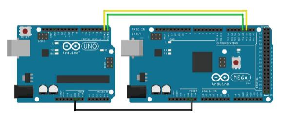
Two Arduino boards are used. The Arduino Uno on the left is the sender and the Arduino
Mega on the right is the receiver. We use the Mega to make it easier to display debugging
information on the computer. The Arduinos are connected together using digitals 0 and 1
(RX and TX) on the Uno and digitals 16 and 17 (RX2 and TX2) on Mega. The receiver
on one needs to be connected to the transmit on the other and vice versa. The Arduinos
also need to have a common reference between the two, this is done by running a ground
wire. The first step in creating a serial communication system is to package the string to
be communicated. In general a packet is comprised of some start byte, a payload (the data
you wish to send), and a checksum to validate your data. Here, the packet is: [0x53]
+[counter value]+[static value]+ [checksum]. The sender code is shown below that
increments our counter and send our packet.
Write the Receiver code for the above send information. [10 marks]