
DATA COMMUNICATION AND NETWORKING: COMPUTER NETWORKING
Networking is the concept of sharing resources and services. A network of computers is a group of interconnected systems sharing resources and interacting using a shared communications link. A network, therefore, is a set of interconnected systems with something to share. The shared resource can be data, a printer, a fax modem, or a service such as a database or an email system. The individual systems must be connected through a pathway (called the transmission medium) that is used to transmit the resource or service between the computers. All systems on the pathway must follow a set of common communication rules for data to arrive at its intended destination and for the sending and receiving systems to understand each other. The rules governing computer communication are called protocols.
CHARACTERISTICS OF A NETWORK
- A resource to share (resource)
- A pathway to transfer data (transmission medium)
- A set of rules governing how to communicate (protocols).
TYPES OF NETWORK COMPUTING
CENTRALIZED COMPUTING
The centralized computing model is where all processing takes place in the central mainframe computer.
Terminals are connected to the central computer and function only as input/output devices. An example of centralized computing to which everyone can relate is using an ATM machine. ATMs function as terminals. All processing is done on the mainframe computer to which the ATMs are connected.
DISTRIBUTED COMPUTING
PCs enable individuals to work at their own computers rather than through a single large computer.
Distributed computing involves multiple computers capable of processing independently. . Task completion by the local computer or other computers on the network
COLLABORATIVE COMPUTING
Collaborative computing enables computers in a distributed computing environment to share processing power in addition to data, resources, and services. In a collaborative computing environment, one computer might borrow processing power by running a program on another computer on the network. Or, processes might be designed so they can run on two or more computers. Collaborative computing cannot take place without a network to enable the various computers to communicate.
TYPES OF NETWORK MODELS
CLIENT/SERVER-BASED NETWORKING
A client/server network consists of a group of user-oriented PCs (called clients) that issue requests to a server. The client PC is responsible for issuing requests for services to be rendered. The server’s function on the network is to service these requests.Some common server types include file servers, mail servers, print servers, fax servers, and application servers.
PEER-TO-PEER NETWORKING
A peer-to-peer network consists of a group of PCs that operate as equals. Each PC is called a peer. The peers share resources (such as files and printers) just like in a server-based network, although no specialized or dedicated server machines exist.
TYPES OF NETWORKS
LOCAL AREA NETWORKS (LANS)
A local area network (LAN) is a group of computers and network communication devices interconnected within a geographically limited area, such as a building or a campus.
CHARACTERISTICS OF LANS
- They transfer data at high speeds (higher bandwidth).
- They exist in a limited geographical area.
- Connectivity and resources and transmission media are managed by the company running the LAN.
WIDE AREA NETWORKS (WANS)
A wide area network (WAN) is interconnection of computers covering large geographical area such as nationwide or internationally. It interconnects LANs.
CHARACTERISTICS OF WANS
- They exist in an unlimited geographical area.
- They usually interconnect multiple LANs.
- They often transfer data at lower speeds (lower bandwidth).
- Connectivity and resources, especially the transmission media, usually are managed by a third-party carrier such as a telephone or cable company.
TYPES OF NETWORK TOPOLOGIES
A topology defines the arrangement of nodes, cables, and connectivity devices that make up the network.it can also be defined as the way in which computers in a network are linked together. It determines the data paths that may be used between any two communicating computers in a network.
1.0 BUS TOPOLOGIES
A bus physical topology is one in which all devices connect to a common, shared cable (sometimes called the backbone).Bus networks broadcast signals in both directions on the backbone cable, enabling all devices to directly receive the signal.
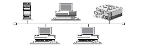
ADVANTAGES
- It is very reliable since any line break down affects the connected computers
- Computer to computer communication is very fast
- Transmission may take different routes between any two communicating stations.
DIS-ADVANTAGES
- It is expensive because of many transmission channels or links required.
2.0 RING TOPOLOGIES
Ring topologies are wired in a circle. Each node is connected to its neighbors on either side, and data passes around the ring in one direction only. Ring topologies are ideally suited for token-passing access methods.
The token passes around the ring, and only the node that holds the token can transmit data.
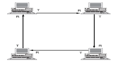
ADVANTAGES
- It is more reliable since a breakdown of one computer does not affect others in the network
- Processing task is distributed to local computer stations thus not reliant to host computer
- If one line between any two computers breaks down alternate routing is possible
DIS-ADVANTAGES
- There is communication delay which is directly proportional to the number of computers in network
- There is duplication of resources at various stations of the network
3.0 STAR TOPOLOGIES
In this configuration, one host computer is connected to various computers in a network. Star topologies require that all devices connect to a central hub. The hub receives signals from other network devices and routes the signals to the proper destinations.
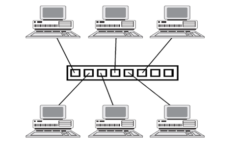
ADVANTAGES
- Data can be shared by all computers
- There is minimal line cost because to connect n computers only n-1 lines are required
- If any computer fail, the entire network is not affected
- Addition of new computers does not increase transmission delays between computers
DIS-ADVANTAGES
- If the central host computer fails, the entire network is affected.
4.0 MESH TOPOLOGY
A mesh topology is really a hybrid model representing an all-channel sort of physical topology. It is a hybrid because a mesh topology can incorporate all the topologies covered to this point. Computers are interconnected.
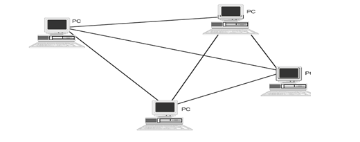
ADVANTAGES
- Breakdown of one station does not affect the entire network
- It is easy to add new stations
- Number of the physical links are reduced
DIS-ADVANTAGES
- Each computer in the network must have a good decision making capability
- If the shared transmission channel breaks down the entire network fails
TYPES OF NETWORKINGCOMPONENTS AND DEVICES
MODEMS
Standard telephone lines can transmit only analog signals. Computers, however, store and transmit data digitally. Modems can transmit digital computer signals over telephone lines by converting them to analog form. Converting one signal form to another (digital to analog in this case) is called modulation. Recovering the original signal is called demodulation. The word “modem” derives from the termsmodulation/demodulation. Modems can be used to connect computer devices or entire networks that are at distant locations. (Before digital telephone lines existed, modems were about the only way to link distant devices.)
REPEATERS
The purpose of a repeater is to extend the maximum range for the network cabling. A repeater is a network device that repeats a signal from one port onto the other ports to which it is connected. A repeater passes on all signals that it receives.
HUBS
Hubs, also called wiring concentrators, provide a central attachment point for network cabling.
BRIDGES
Bridges extend the maximum size of a network. A repeater passes on all signals that it receives. A bridge is more selective and passes only those signals targeted for a computer on the other side. A bridge can make this determination because each device on the network is identified by a unique physical address. Each packet that is transmitted bears the address of the device to which it should be delivered.
ROUTERS
Internetwork connectivity devices, such as routers, Can use network address information to assist in the efficient delivery of messages. Delivering packets according to logical network address information is called routing. The common feature that unites internetwork connectivity devices (routers and brouters) is that these devices can perform routing
BROUTERS
A brouter is a router that also can act as a bridge. A brouter attempts to deliver packets based on network protocol information, but if a particular Network layer protocol isn’t supported, the brouter bridges the packet using device addresses.
GATEWAYS
Gateways connect dissimilar environments by removing the layered protocol information of incoming packets and replacing it with the packet information necessary for the dissimilar environment
NETWORK ARCHITECTURES
Network architecture is the design specification of the physical layout of connected devices. This includes the cable being used (or wireless media being deployed), the types of network cards being deployed, and the mechanism through which data is sent on to the network and passed to each device.
NETWORK SERVICES
Network services are the basic reason we connect computers. Services are what a company wants to have performed or provided. Based on the services a company wants to utilize, the company purchases a specific program and operating system. Common services available on computer networks are:
Basic Connectivity Services – The PCs in a network must have special system software that enables them to function in a networking environment.
Redirector Service – A network client must have a software component called a redirector. In a typical standalone PC, I/O requests pass along the local bus to the local CPU. The redirector intercepts I/O requests within the client machine and checks whether the request is directed toward a service on another computer. If it is, the redirector directs the request toward the appropriate network entity. The redirector enables the client machine to send information out of the computer, provided that a transmission pathway exists.
Server Service – A network server machine must have a component that accepts I/O requests from clients on the network and that fulfills those requests by routing the requested data back across the network to the client machine. In Windows NT, the server service performs the role of fulfilling client requests.
File Services – File services enable networked computers to share files with each other.
File Transfer Services – FTP uses communication software to dial up another computer and transfer files using a modem or a direct serial connection. With a network, users have constant access to high-speed data transfer without leaving their desks or dialing another computer. Making a file accessible on a network is as easy as moving it into a shared directory.
Database Services – Database services enable applications to be designed in separate client and server components, such applications frequently are called client/server databases.
ACCESS METHODS
An access method is a set of rules governing how the network nodes share the transmission medium. The rules for sharing among computers are similar to the rules for sharing among humans in that they both boil down to a pair of fundamental philosophies:
1) First come, first served and 2) Take turns. These philosophies are the principles defining the three most important types of media access methods:
-Contention. Contention means that the computers are contending for use of the transmission medium. Any computer in the network can transmit at any time (first come, first served). This system breaks down when two computers attempt to transmit at the same time, in which case a collision occurs.
-Polling. One device is responsible for polling the other devices to see whether they are ready for the transmission or reception of data. Polling-based systems require a device (called a controller, or master device) to poll other devices on the network to see whether they are ready to either transmit or receive data. This access method is not widely used on networks because the polling itself can cause a fair amount of network traffic. A common example of polling is when your computer polls its printer to receive a print job.
–Token passing. The computers take turns using the transmission medium. Token passing utilizes a frame called a token, which circulates around the network. A computer that needs to transmit must wait until it receives the token, at which time the computer is permitted to transmit. When the computer is done transmitting, it passes the token frame to the next station on the network.
NETWORK ADAPTER CARD
A network adapter card links a PC with the network cabling system. The network adapter card fits into one of the PC’s expansion slots. The card has one or more user-accessible ports to which the network cabling medium is connected.
How a Network Card Works
In order to communicate (send and receive information to and fro other machines) network cards use signals and clocking.
Signals Two basic types of signals are used with transmission media: analog and digital.
Analog Signals-Analog signals constantly vary in one or more values, and these changes in values can be used to represent data. Analog waveforms frequently take the form of sine waves.
The two characteristics that define an analog waveform are as follows:
. Frequency. Indicates the rate at which the waveform changes. Frequency is associated with the wavelength of the waveform, which is a measure of the distance between two similar peaks on adjacent waves. Frequency generally is measured in Hertz (Hz), which indicates the frequency in cycles per second.
. Amplitude. Measures the strength of the waveform. Each of these characteristics—frequency and amplitude—can be used to encode data.
Digital Signals-Digital signals have two discrete states. These states are either “off” or “on.”
Clocking- Clocking is the mechanism used to count and pace the number of signals being sent and received. Signals are expected to be sent in a continuous flow, representing the start and ending of the data. Clocking is the mechanism used by the network adapter card to determine how much data has been sent. For example, if a network card is designed to transmit data at 20,000 Megahertz a second, other cards receiving this data will also read the data at 20,000MHz a second. Clocking is a mechanism used by all network adapter cards to measure how much data has been sent or received. (A good example of clocking is when a person taps his feet to keep the time to music. The person doing the tapping expects a set number of music beats per measure; computer network cards also expect so many signals per second.
A clocking mechanism used by some network cards is oversampling. With oversampling, the receiving network adapter card samples, or reads the signals, at a higher frequency than that at which the data is sent.
TRANSMISSION MEDIA
CHARACTERISTICS
Each type of transmission media has special characteristics that make it suitable for a specific type of service. You should be familiar with these characteristics for each type of media:
. Cost
. Installation requirements
. Bandwidth
. Band usage (baseband or broadband)
. Attenuation
. Immunity from electromagnetic interference
These characteristics are all important. When you design a network for a company, all these factors play a role in the decision concerning what type of transmission media should be used.
Cost
Often the fastest and most robust transmission media is desired, but a network designer must often settle for something that is slower and less robust, because it more than suffices for the business solution at hand. The major deciding factor is almost always price. As with nearly everything else in the computer field, the fastest technology is the newest, and the newest is the most expensive. Over time, economies of scale bring the price down, but by then, a newer technology comes along.
Installation Requirements
Installation requirements typically involve two factors. One is that some transmission media require skilled labor to install. The second has to do with the actual physical layout of the network. Some types of transmission media install more easily over areas where people are spread out, whereas other transmission media are easier to bring to clusters of people or a roaming user.
Bandwidth
The term bandwidth refers to the measure of the capacity of a medium to transmit data. A medium that has a high capacity, for example, has a high bandwidth, whereas a medium that has limited capacity has a low bandwidth.
Data transmission rates are frequently stated in terms of the bits that can be transmitted per second. An Ethernet LAN theoretically can transmit 10 million bits per second and has a bandwidth of 10 megabits per second (Mbps). The bandwidth that a cable can accommodate is determined in part by the cable’s length. A short cable generally can accommodate greater bandwidth than a long cable, which is one reason all cable designs specify maximum lengths for cable runs. Beyond those limits, the highest-frequency signals can deteriorate, and errors begin to occur in data signals. You can see this by taking a garden hose and snapping it up and down. You can see the waves traveling down the hose get smaller as they get farther from your hand. This loss of the wave’s amplitude represents attenuation, or signal degradation. Band Usage (Baseband or Broadband)
The two ways to allocate the capacity of transmission media are with baseband and broadband transmissions. Baseband devotes the entire capacity of the medium to one communication channel. Broadband enables two or more communication channels to share the bandwidth of the communications medium.
Baseband is the most common mode of operation. Most LANs function in baseband mode, for example. Baseband signaling can be accomplished with both analog and digital signals.
Multiplexing
Multiplexing is a technique that enables broadband media to support multiple data channels.
Attenuation
Attenuation is a measure of how much a signal weakens as it travels through a medium.
Attenuation is a contributing factor to why cable designs must specify limits in the lengths of cable runs. When signal strength falls below certain limits, the electronic equipment that receives the signal can experience difficulty isolating the original signal from the noise present in all electronic transmissions.
Electromagnetic Interference
Electromagnetic interference (EMI) consists of outside electromagnetic noise that distorts the signal in a medium. When you listen to an AM radio, for example, you often hear EMI in the form of noise caused by nearby motors or lightning. Some network media are more susceptible to EMI than others.
Crosstalk is a special kind of interference caused by adjacent wires. Crosstalk occurs when the signal from one wire is picked up by another wire. You may have experienced this when talking on a telephone and hearing another conversation going on in the background. Crosstalk is a particularly significant problem with computer networks because large numbers of cables often are located close together, with minimal attention to exact placement.
CABLE MEDIA
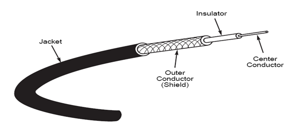
Coaxial Cable
Coaxial cables were the first cable types used in LANs. Coaxial cable gets its name because two conductors share a common axis; the cable is most frequently referred to as a “coax.” A type of coaxial cable that you may be familiar with is your television cable. The components of a coaxial cable are as follows:
. A center conductor, although usually solid copper wire, is sometimes made of stranded wire.
. An outer conductor forms a tube surrounding the center conductor. This conductor can consist of braided wires, metallic foil, or both. The outer conductor, frequently called the shield, serves as a ground and also protects the inner conductor from EMI.
. An insulation layer keeps the outer conductor spaced evenly from the inner conductor.
. A plastic encasement (jacket) protects the cable from damage.
Types of Coaxial Cable.
Thinnet
Thinnet is a light and flexible cabling medium that is inexpensive and easy to install.
Thicknet
Thicknet is thicker than Thinnet. Thicknet coaxial cable is approximately 0.5 inches (13 mm) in diameter. Because it is thicker and does not bend as readily as Thinnet, Thicknet cable is harder to work with. A thicker center core, however, means that Thicknet can carry more signals a longer distance than Thinnet. Thicknet can transmit a signal approximately 500 meters (1,650 feet).
Thicknet can be used to connect two or more small Thinnet LANs into a larger network.
Because of its greater size, Thicknet is also more expensive than Thinnet. However, Thicknet can be installed relatively safely outside, running from building to building.
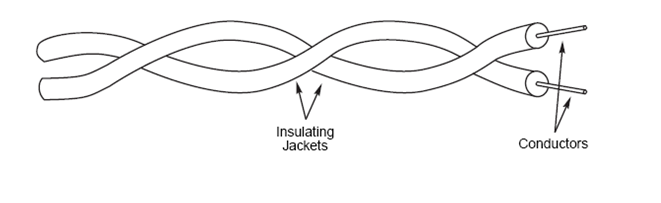
Twisted-Pair Cable
Twisted-pair cable is inexpensive to install and offers the lowest cost per foot of any cable type. Your telephone cable is an example of a twisted-pair type cable. A basic twisted-pair cable consists of two strands of copper wire twisted together. The twisting reduces the sensitivity of the cable to EMI and also reduces the tendency of the cable to radiate radio frequency noise that interferes with nearby cables and electronic components, because the radiated signals from the twisted wires tend to cancel each other out.
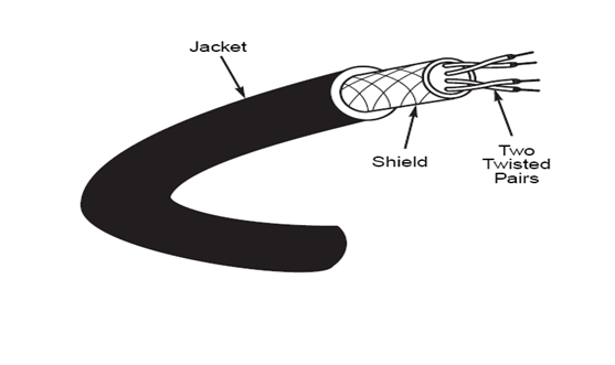
Shielded Twisted-Pair (STP) Cable
Shielded twisted-pair cabling consists of one or more twisted pairs of cables enclosed in a foil wrap and woven copper shielding.
The shield is connected to the ground portion of the electronic device to which the cable is connected. A ground is a portion of the device that serves as an electrical reference point, and usually, it is literally connected to a metal stake driven into the ground. A properly grounded shield prevents signals from getting into or out of the cable.
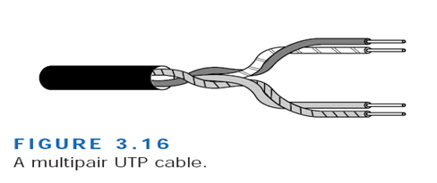
Unshielded Twisted-Pair (UTP) Cable
Unshielded twisted-pair cable doesn’t incorporate a braided shield into its structure. Several twisted pairs can be bundled together in a single cable. These pairs are typically color-coded to distinguish them. UTP cable is the least costly of any cable type and cable is easy to install.
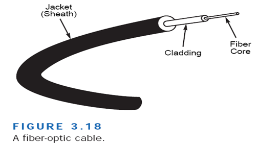
Fiber-Optic Cable
Fiber-optic cable is the ideal cable for data transmission. Not only does this type of cable accommodate extremely high bandwidths, but it also presents no problems with EMI and supports durable cables and cable runs as long as several kilometers. The two disadvantages of fiber-optic cable, however, are cost and installation difficulty. Despite these disadvantages, fiber-optic cable is now often installed into buildings by telephone companies as the cable of choice.
The center conductor of a fiber-optic cable is a fiber that consists of highly refined glass or plastic designed to transmit light signals with little loss. A glass core supports a longer cabling distance, but a plastic core is typically easier to work with. The fiber is coated with a cladding or a gel that reflects signals back into the fiber to reduce signal loss. A plastic sheath protects the fiber. A fiber-optic network cable consists of two strands separately enclosed in plastic sheaths. One strand sends and the other receives. Two types of cable configurations are available: loose and tight configurations. Loose configurations incorporate a space between the fiber sheath and the outer plastic encasement; this space is filled with a gel or other material. Tight configurations contain strength wires between the conductor and the outer plastic encasement.
Fiber-optic cable can support high data rates (as high as 200,000Mbps) even with long cable runs. Although UTP cable runs are limited to less than 100 meters with 100Mbps data rates, fiber optic cables can transmit 100Mbps signals for several kilometers.
COMPARISON OF CABLE MEDIA
| Cable Type | Cost | Installation | Capacity | Range | EMI | |
| Coaxial Thinnet | Less than STP | Inexpensive/easy | 10Mbps typical | 185 m | Less sensitive than UTP | |
| Coaxial Thicknet | Greater than STP less than fiber | Easy | 10Mbps typical | 500 m | Less sensitive than UTP | |
| Shielded twisted pair | Greater than UTP. Less than Thicknet | Fairly easy | 16Mbps typical up to 500Mbps | 100 m typical | Less sensitive than UTP | |
| Unshielded twisted pair | Lowest | Inexpensive/easy | 10Mbps typical up to 100Mbps | 100 m typical | Most sensitive | |
| Fibre-optic | Highest | Expensive/difficult | 100Mbps typical | 10s’ of km | Insensitive |
DATA TRANSMISSION
Simplex Transmission
Data in a Simplex transmission is always one way. Simplex transmission are not often used because it is not possible to send back error or control signals to the transmit end. It’s like a one-way street. An example of simplex is a Television, or Radio.
Half Duplex Transmission
A half-duplex transmission can send and receive in one direction, but not at the same time. It’s like a one-lane bridge where two-way traffic must give way in order to cross. Only one end transmits at a time, the other end receives.
In addition, it is possible to perform error detection and request the sender to retransmit information that arrived corrupted. In some aspects, you can think of Internet surfing as being half-duplex, as a user issues a request for a web document, then that document is downloaded and displayed before the user issues another request.
Another example of half-duplex is talkback radio, and CB Radio (Citizens Band). You might have seen movies where a truck driver communicates to each other, and when they want the other person to speak they say “over”. This is because only one person can talk at a time
Full Duplex
Data can travel in both directions simultaneously. There is no need to switch from transmit to receive mode like in half duplex. It is like a two lane bridge on a two-lane highway. Have you ever watched these television talk shows where the host has a number of people on the show, and they all try to talk at once. Well, that’s full duplex!
Of course, in the world of data communications, full duplex allows both way communications simultaneously. Another example can be a consumer, which uses a cable connection not only, receives TV channels, but also the same cable to support their phone and Internet surfing. All these activities can occur simultaneously.
WIRELESS MEDIA
The extraordinary convenience of wireless communications has placed an increased emphasis on wireless networks in recent years. Technology is expanding rapidly and will continue to expand into the near future, offering more and better options for wireless networks. Presently, you can subdivide wireless networking technology into three basic types corresponding to three basic networking scenarios:
- Local area networks (LANs). Occasionally you will see a fully wireless LAN, but more typically one or more wireless machines function as members of a cable-based LAN.
- Extended local networks. A wireless connection serves as a backbone between two LANs. For instance, a company with office networks in two nearby but separate buildings could connect those networks using a wireless bridge.
- Mobile computing. A mobile machine connects to the home network using cellular or satellite technology.
Reasons for Wireless Networks
- Spaces where cabling would be impossible or inconvenient. These include open lobbies, inaccessible parts of buildings, older buildings, historical buildings where renovation is prohibited, and outdoor installations.
- People who move around a lot within their work environment. Network administrators, for instance, must troubleshoot a large office network. Nurses and doctors need to make rounds at a hospital.
- Temporary installations. These situations include any temporary department set up for a specific purpose that soon will be torn down or relocated.
- People who travel outside of the work environment and need instantaneous access to network resources.
- Satellite offices or branches, ships in the ocean, or teams in remote field locations that need to be connected to a main office or location.
Wireless Communications with LANs
- Infrared Transmission
You use an infrared communication system every time you control your television with a remote control. The remote control transmits pulses of infrared light that carry coded instructions to a receiver on the TV. This technology also is used for network communication.
Four varieties of infrared communications are as follows:
. Broadband optical telepoint This method uses broadband technology. Data transfer rates in this high-end option are competitive with those for a cable-based network.
. Line-of-sight infrared Transmissions must occur over a clear line-of-sight path between transmitter and receiver.
. Reflective infrared Wireless PCs transmit toward a common, central unit, which then directs communication to each of the nodes.
. Scatter infrared. Transmissions reflect off floors, walls, and ceilings until (theoretically) they finally reach the receiver. Because of the imprecise trajectory, data transfer rates are slow. The maximum reliable distance is around 100 feet.
Infrared transmissions are typically limited to within 100 feet. Within this range, however, infrared is relatively fast.
- Laser Transmission
High-powered laser transmitters can transmit data for several thousand yards when line-of-sight communication is possible. Lasers can be used in many of the same situations as microwave links. On a LAN scale, laser light technology is similar to infrared technology. Laser light technology is employed in both LAN and WAN transmissions, though it is more commonly used in WAN transmissions.
- Narrow-Band Radio Transmission
In narrow-band radio communications (also called single-frequency radio), transmissions occur at a single radio frequency. The range of narrow-band radio is greater than that of infrared, effectively enabling mobile computing over a limited area. Neither the receiver nor the transmitter must be placed along a direct line of sight; the signal can bounce off walls, buildings, and even the atmosphere, but heavy walls, such as steel or concrete enclosures, can block the signal.
- Spread-Spectrum Radio Transmission
Spread-spectrum radio transmission is a technique originally developed by the military to solve several communication problems. Spread-spectrum improves reliability, reduces sensitivity to interference and jamming, and is less vulnerable to eavesdropping than single-frequency radio. Spread-spectrum radio transmissions are commonly used for WAN transmissions that connect multiple LANs or network segments together.
- Microwave
Microwave technology has applications in all three of the wireless networking scenarios: LAN, extended LAN, and mobile networking.
Microwave communication can take two forms: terrestrial (ground) links and satellite links. The frequencies and technologies employed by these two forms are similar, but distinct differences exist between them.
Mobile computing is a growing technology that provides almost unlimited range for traveling computers by using satellite and cellular phone networks to relay the signal to a home network. Mobile computing typically is used with portable PCs or personal digital assistant (PDA) devices.
Three forms of mobile computing are as follows:
. Packet-radio networking The mobile device sends and receives network-style packets via satellite. Packets contain a source and destination address, and only the destination device can receive and read the packet.
. Cellular networking The mobile device sends and receives cellular digital packet data (CDPD) using cellular phone technology and the cellular phone network. Cellular networking provides very fast communications
. Satellite station networking Satellite mobile networking stations use satellite microwave technology.